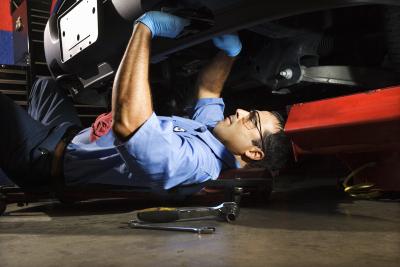
Replacing a ball joint on a Chevy Tahoe truck depends on the year of the truck and if you're changing the upper or lower joint. For more recent models (made since 2007), the lower ball joint can be removed and replaced within its control arm, but the upper ball joints require replacing the entire control arm. Check with your mechanic in the case of older vehicles, as they often require you to take the control arm to a machine shop.
Raise the truck's front end and support it on jack stands, then remove the front wheel for the ball joint you are changing.
Disconnect the stabilizer bar's link bolts from the control arm using a wrench. Remove the lower mounting fasteners on the shock absorber with the wrench.
Support the upper control arm and steering knuckle to the top of the shock absorber using rope or wire.
Loosen the ball joint nut by a few turns with the wrench and then break the ball joint loose from the steering knuckle using a ball-joint separator or a hammer and drift. Remove the nut after braking the joint loose.
Remove the pivot nuts and bolts for the control arm with the wrench and pull the arm from the frame brackets.
Mount the control arm inside a bench vise.
Knock back the crimped areas on the ball joint using a hammer and chisel.
Press the ball joint out of the control arm using a ball-joint press from an auto-parts store or equipment-rental yard.
Press the replacement ball joint into the control arm, making sure the ball-joint press adapter only applies its force to the joint's flange. Crimp or stake the joint into place with the hammer and chisel once the joint is completely pressed in.
Place the control arm within the frame brackets and install the bolts and nuts without tightening them. Connect the ball joint to the steering knuckle with a new nut and tighten that nut to 92 ft-lbs.
Reconnect the torsion bar (if equipped), shock-absorber mounting fasteners and stabilizer link to the control arm.
Connect the wheel back on the truck and lower it off the jack stands, then tighten the control arm pivot bolt nuts to 129 ft-lbs.
Raise and support the truck with the jack stands and remove the wheel. Raise a floor jack under the lower control arm to remove the spring pressure from the upper arm.
Mark the relationship between the adjusting cams and the control-arm frame brackets using a marker or paint. Unbolt the brake hose and speed-sensor bracket from the control arm with a wrench, then remove the speed sensor and detach the wiring-harness bracket from the steering knuckle.
Loosen the nut for the upper ball joint by a few turns with the wrench without removing it. Use a separator tool to break the joint loose from the steering knuckle and then remove the nut.
Remove the arm's pivot nuts and bolts and remove the control arm.
Place the replacement control arm within its frame brackets and install the bolts and nuts loosely. Attach the ball joint to the knuckle and tighten a new nut to 37 ft-lbs.
Connect the wheel-speed sensor and the wiring-harness bracket to the steering knuckle and connect the brake-hose/speed-sensor bracket to the control arm.
Reconnect the wheel and lower the vehicle, then tighten the control arm pivot nuts to 140 ft-lbs.