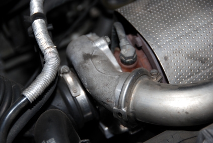
Most turbochargers have seven basic parts, three stationary and four moving. The stationary parts include the compressor housing, the turbine housing and the center cartridge housing that connects them. The moving parts include the compressor wheel, the turbine (exhaust) wheel, the shaft that connects the two wheels and the bearing that holds the shaft. Turbos are fairly modular. The manufacturer can often use any one component in conjunction with several others, leading to thousands of possible turbocharger housing and wheel combinations.
The TD04-9B turbo appeared primarily on the twin-turbocharged, 24-valve 6G72 V-6 used in Mitsubishi 3000GT VR-4s and Dodge Stealth R/T twin-turbos. In stock form the TD04-9B turbo produced enough boost to make 319 horsepower and 315 pound-feet of torque, but was capable of producing over 400 horsepower when used with a boost controller. The larger TD04-13G turbo is a popular upgrade over the 9B. The 13G is about 2 percent more efficient and flows about 360 cubic feet of air per minute compared to the 9B's 265, giving it about another 100 to 150 horsepower in potential.
All manufacturers use a slightly different system to designate their housing design/size and compressor/turbine size and design. In the Mitsubishi Heavy Industries system, the first series of numbers and letters designate the turbine housing size and design, as well as the exhaust turbine wheel size and design. The second code designates the compressor wheel and housing size and design. For example, a TD04-9B turbocharger uses a TD04 turbine housing and wheel, and a 9B compressor wheel and housing.
Wheel size uses two basic measurements, the inducer diameter and exducer diameter. The wheel's outer diameter is the exducer and the smaller inner circle is the inducer (where the air comes in). The 9B wheel's exducer measures 1.930 inches in diameter, and the inducer measures 1.365 inches with a 50 trim. In the MHI system, the exducer diameter rises with number. For example, the 13G has a 2.00-inch exducer and 1.580-inch inducer, and the 15G has a 2.187-inch exducer and a 1.625-inch inducer.
The letter following the numbers indicated the design of the compressor blades. In general, lower-letter compressor trims are more efficient over a higher airflow rate and pressure range, but higher-letter compressor wheels can perform at lower airflow rates and spin to a higher rpm. For example, a 14B wheel peaks at 76-percent efficiency within a fairly small range from 0.90 to 0.11 meters/per second of airflow and a 1.4 to 1.8 pressure range. A 14G wheel maintains its higher 77-percent efficiency rate from 0.90 meter/second to 0.122 meters/second, and from a pressure range of 1.42 all the way up to 2.1. However, the G-trim's efficiency drops off far quicker than the B-trim's, making it a less flexible design than the B-trim. The 9B has a very broad efficiency range compared to larger and more aggressive trims. It peaks at 76 percent from a 1.4 to 1.7 pressure ratio, but maintains a 70 percent efficiency all the way from 1.4 to 2.6 and 0.3 to 0.11 meters/second of airflow.