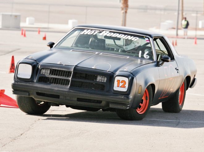
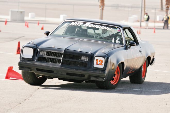
When it comes down to it, there’s no easy way to explain the engineering behind suspension design. It’s a complex science where tweaking one variable affects a dozen other variables, and the resulting domino effect can be quite frustrating for a weekend warrior trying to shave off a tenth or two on the autocross. To compound the situation, once you start diving into suspension tuning, you’re met with a roadblock of fancy terminology that few people can clearly explain. That’s what this story is all about. Think of it as a glossary of common suspension terms defined by the leading engineers and manufacturers in the aftermarket. We got our field of experts to uncover the secrets behind everything from Ackerman and antisquat, to scrub radius and instant center. Let’s dig in!
Ackerman
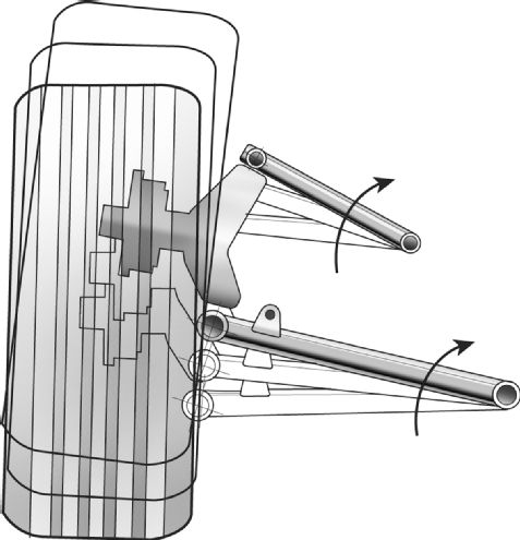
As a car negotiates a corner, the inside front wheel travels in a tighter radius than the outside wheel. Ideally, it would be possible for the inside tire to turn at a tighter angle than the outside tire. Ackerman refers to any tricks or tweaks in the suspension geometry to help the inside tire travel in a tighter arc, but this can be difficult to accomplish. One method is to set the front tires to toe-out. While this does help situate the inside tire at a more advantageous angle during cornering, it also points the outside tire in the wrong direction. Alternately, some chassis builders have experimented with intentionally dialing in a small amount of bumpsteer to toe-out the tires during cornering. Ultimately, the benefit of Ackerman geometry is up for debate. Many experts agree that its benefits are questionable in a street car, and some racers swear by it while others don’t. “The theory behind Ackerman geometry is that without it, the inside tire scrubs and chirps, resulting in a loss of cornering speed. On some tracks, you can also set a car up for reverse Ackerman, where the outside tire turns at a sharper angle than the inside tire,” Dale Schwartz of Schwartz Performance explains.
Antisquat

When most street cars accelerate forward, weight transfers rearward and causes the back of the car to squat. In an effort to enhance the forward bite of the rear tires, the suspension can be set up to counteract this squatting force and drive the rearend housing into the ground. Aptly referred to as antisquat, this effect is very well optimized in drag cars, but it can also benefit road course machines as well. “Drag cars can actually have so much antisquat that they raise the back end of the car during acceleration. What’s happening is that as the pinion gear rotates the ring gear and torques the rearend housing, that force is being used to drive the tires into the pavement,” Matt Jones of Art Morrison Enterprises (AME) explains. In cars with a four-link rear suspension, angling the control arms upward to move the instant center height closer to the center of gravity height increases antisquat. “Antisquat is calculated based on the instant center location in relation to the center of gravity. As long as it doesn’t compromise other aspects of suspension geometry, antisquat can help put the power down when exiting a corner.”
Bumpsteer
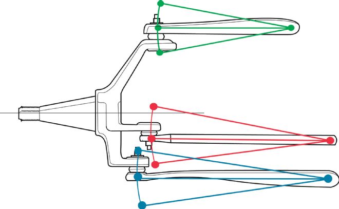
Bumpsteer is sometimes described as how much the steering direction jerks when a car hits a bump, but that’s just part of the story. A more complete description of bumpsteer is the amount and direction the toe changes during suspension travel. This condition changes the steering angle as the suspension compresses and rebounds. Since the steering tie rods and the upper and lower control arms travel in separate arcs, it is this disparity in movement that causes the front tires to toe-in or toe-out during suspension travel. According to Steve Gorski of Unisteer: “The idea is to get the pivot points of the steering rack to match the pivot points of the chassis as closely as possible. Global West’s Doug Norrdin concurs: “The key to reducing bumpsteer is making the arcs, the tie rods, and control arms travel as similar as possible. Some people think that the bumpsteer will be minimized if the tie rods are parallel to the ground, but that’s not entirely accurate,” he explains. “After setting the ride height, at our shop we dial 2 inches of suspension travel in the upward and downward direction, which is quite a bit. Then the bumpsteer can be adjusted by changing tie rod length and height, or if that’s not enough, by moving the entire steering rack. On many production cars, this might get you 3 inches of travel in which you have little to no bumpsteer, with some bumpsteer starting to creep in at the extreme ends of suspension travel. Any time you lower a car, you have to readjust the bumpsteer.”
Camber and Caster

Camber and caster are very easy to understand, yet both profoundly impact the handling of a car. When viewed from the front of a car, camber refers to the direction in which the tops of the tires are leaning. A tire that leans inward has negative camber, while a tire that leans outward has positive camber. Since the laws of physics force the outside tire to lean outward during cornering—which reduces the contact patch and cornering grip—most modern suspension systems have negative camber built-in. “Negative camber increases the contact patch, and increases turning thrust to help a car change directions. Lower sidewall tires give less thrust, and taller sidewalls allow running more negative camber,” says Danny Nix of Classic Performance Products (CPP).
On the other hand, caster refers to the angle the spindle is set at when viewed from the side of a car. If an imaginary line was drawn from the upper ball joint to the lower ball joint, the angle of that line would reflect the caster. With positive caster the spindle angles rearward, while with negative caster the spindle angles forward. “The distance from the contact patch to steering axis is called the trail, and the larger the trail, the more the car wants to go straight,” Nix explains. “Likewise, the more positive caster you have, the more camber you can gain while turning. Increasing caster increases steering effort and the self-centering effect of the steering wheel. The downside is that it also reduces steering feedback.”
Camber Gain

If negative camber increases the size of the contact patch during cornering—and therefore increasing grip—camber gain expands upon that concept. Proper chassis tuning can result in a suspension that yields an increase in negative camber as body roll increases, a condition known as camber gain. “One of the biggest performance limitations of a stock suspension is the limited amount of camber gain that can be achieved with them. In fact, compressing the suspension in many muscle cars results in positive camber, which is the exact opposite of what you want,” says Roadster Shop’s Jeremy Gerber. “There isn’t much you can do to increase camber gain with a stock suspension because it’s difficult to move the pickup points around. You can lower the attachment point of the upper control arm, but that’s about it. With an aftermarket frame, however, you can radically change the length of the control arms, and relocate the pickup points. A car like a stock C6 Corvette will pick up half a degree of negative camber for every inch of suspension travel. We set up our frames to pick up 1 degree of negative camber for every inch of travel.”
Instant Center
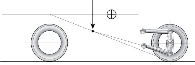
Conceptualizing instant center is best done by looking at the side profile of a car. If you drew a line from the back of the rear control arms to the front of the rear control arms, then extended the lines to the front of the car, a car’s instant center is the point where those lines intersect. Raising the instant center, or moving it farther rearward, results in a chassis that transfers weight from the front to the rear more quickly. Lowering the instant center, or moving it farther forward, decreases weight transfer. “There are lots of opinions on where the instant center should be positioned, but we’ve learned a lot through track testing,” RideTech’s Bret Voelkel explains. “With our four-link rear suspension systems, we have had positive results by running the lower control arm parallel to the ground, and angling the upper control arms downward 2 to 3 degrees. This puts the instant center right at the back of the crankshaft, and gives a car excellent forward bite. If the upper and lower control arms are close to parallel, it puts the instant center way out in front of the car and compromises traction.”
Roll Center
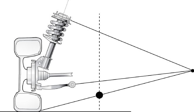
The point in space where the suspension and body rotates as a car leans from side to side is the roll center. If plotting a scale drawing of a suspension on paper, the first step in determining the roll center is to establish the instant center location based on the angles of the control arms. Next, a line must be drawn from the left and right contact patches of the tires to the instant center. The intersection point of these two lines is the roll center, which can be located above or below the ground. “Moving the roll center changes the roll stiffness of a vehicle,” Matt Jones of AME says. “The farther away from the center of gravity the roll center is, the more a car will roll. Raising the roll center reduces body roll. That said, the roll center couldn’t be moved much at all within the confines of stock suspension pickup points.”
Roll Steer
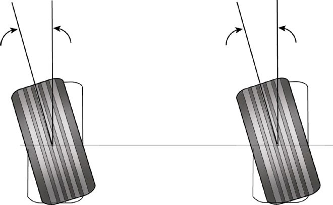
Just like bumpsteer changes the steering angle of the front tires, roll steer changes the angle of the rearend housing, resulting in understeer or oversteer. This can happen for several different reasons. Imagine a leaf-spring car hustling hard around a left-hand turn. Since the right-side spring increases in overall length as it compresses, which lengthens the wheelbase on that side of the car, the rearend will point to the right, inducing roll oversteer. For street cars, a slight degree of roll understeer results in more predictable handling, and this can be accomplished by relocating the lower control arm in cars with a four-link or torque-arm style rear suspension. Angling the lower control arms downward shortens up the wheelbase on the right side of the car when turning left, which increases understeer. Pointing the lower control arms upward has the opposite effect. As an alternative solution, Hot Rods to Hell’s unique center-drive truck arm system uses a crossmember positioned 51 inches in front of the rear axle centerline. “Since the lower control arms are so long and anchored to the center of the car, there is no change in wheelbase as the suspension compresses,” Steve McClenon explains. “This system eliminates roll steer and binding. The central mounting also eliminates chassis flex and results in incredible forward bite.”
Roll Stiffness
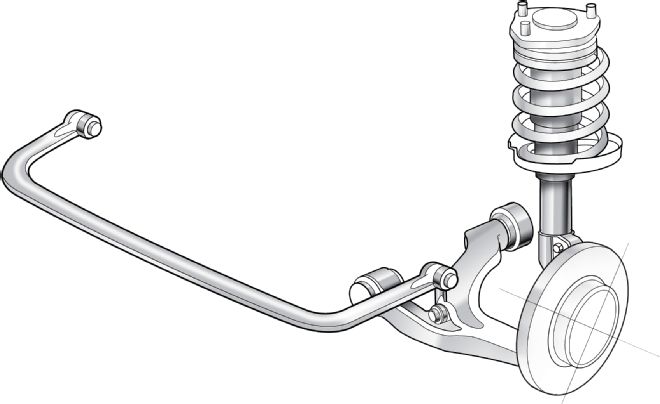
A suspension’s ability to resist body roll is known as roll stiffness. In essence, it is simply the combined stiffness of the springs and sway bars. Certain applications call for stiff springs and smaller sway bars, while softer springs and larger sway bars are more prevalent in other applications. For cars that see both street and track duty, many suspension tuners prefer a spring that is barely stiff enough to prevent a car from bottoming out. This affords a more compliant ride quality, and enables the tires to more closely follow the contours of the road. “The most important factor is determining how a car will be used. For a street car that sees occasional track time, we recommend softer springs and larger sway bars,” Heidts’ Mike Hawley explains. “If you’re setting up a car that will only be driven on the autocross, you can get away with stiffer springs and smaller sway bars. If that’s still not stiff enough, you can make the sway bars even bigger. Every application is different, so we ask our customers lots of questions to make sure we know their goals for their car. We can get things pretty close right off the bat, but we will let our customers swap out springs if necessary.”
Scrub Radius
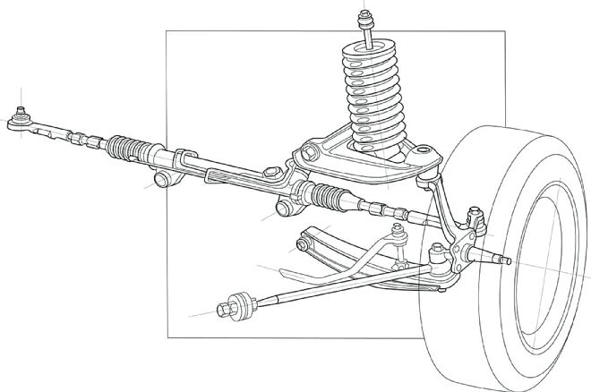
Like bumpsteer, scrub radius is something that must be minimized for optimal handling. Let’s say you’re looking at the front suspension while standing directly in front of a car. If a line was drawn through the upper and lower ball joint, the angle this line creates with the ground is the kingpin inclination. If a second line was drawn from the wheel centerline to the ground, the distance between it and the kingpin inclination line is the scrub radius. Bumps and cornering loads transmitted through the tires exert a twisting force on the steering system that’s proportional to the length of the scrub radius, so it’s imperative to keep it to a minimum. Consequently, cars with zero scrub radius can be driven easily without power steering. “Scrub radius can be kept to a minimum by keeping the ball joints as close to the wheel centerline as possible,” RideTech’s Bret Voelkel says. “You can also affect scrub radius significantly by changing wheel offset. Most of the time, you end up with a scrub radius that’s in an acceptable range by special coincidence.”
Shock Compression and Rebound
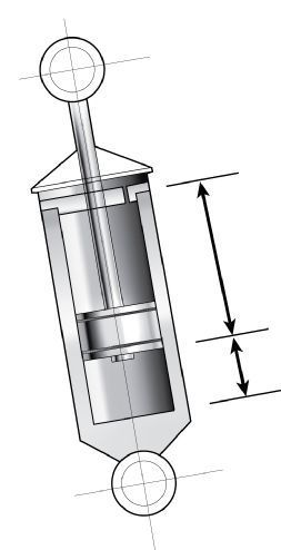
In the rest of the world, shocks are called spring dampers. That’s because the springs control the motion of a car’s body, while the shocks control the gyrating motion of the springs. This is accomplished by pushing the piston into the shock body during compression, and after dissipating the shock load, it extends back out of the body during rebound. “When designing a shock, we put it on a shock dyno to test how it reacts to carefully measured units of force in both compression and rebound. The pounds of force exerted on the shock rod is charted on the Y-axis of a graph, and the acceleration of the rod in inches per second is mapped on the X-axis,” Stacy Tucker of Detroit Speed and Engineering (DSE) explains. “A shock must be matched to the spring rate, and the rest of the suspension. After we build a prototype shock and install it on a car, we take it on a very specific street route, test it at the track, and drive some more on the street. During this process, we’ll fine-tune the compression, rebound, and jounce bump characteristics. This can take several months to complete. Overall vehicle weight, front and rear axle weight, wheelbase length, track width, suspension geometry, and spring location relative to the tire all affect how a shock must be valved.”
Spring Rate
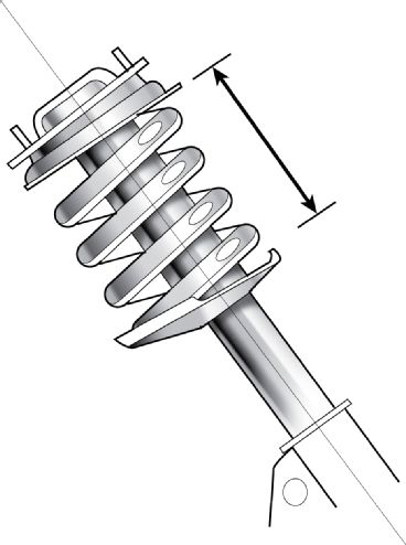
The amount of force required to compress a spring 1 inch is its spring rate. For example, a 400 lb-in spring requires 400 pounds of force to compress 1 inch. Wheel rate, on the other hand, is the actual spring rate as measured at the wheels. The length of the control arms creates a linkage ratio in the suspension, which means that adding 100 lb-in of spring rate increases wheel rate by a lesser amount. Furthermore, for any given wheel rate, positioning a spring closer to the control arm mounting points requires using a stiffer spring rate. As such, it’s impossible to compare the spring rate from one model of car to another. Moreover, when shopping for springs, hot rodders have the option of linear and variable rate units. “With a linear rate spring, the rate is constant throughout the suspension travel, whereas a variable rate spring starts out soft and gets stiffer as it’s compressed,” explains DSE’s Stacy Tucker. “Variable-rate springs are used more in OEM applications because they require very specific suspension tuning requirements. Since ride heights, wheel sizes, and vehicle weight are all over the map with hot rods, linear rate springs often work more effectively.”
Toe
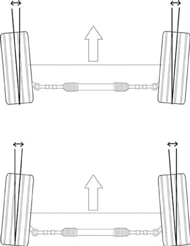
Let’s say you’re in a helicopter looking straight down at the roof of a car. The suspension’s toe angle is how much the front of the tires point inward or outward. Toe-in is where the front of the tires points inward, and toe-out is where the front of the tires points outward. Changing this angle is easily accomplished by adjusting the tie rods. “Toe-in increases stability, but the trade-off is that it makes a car less responsive. If you have very wide front tires, you can dial in some toe-in to intentionally scrub the tires to build heat,” CPP’s Danny Nix explains. “Conversely, toe-out reduces stability and makes a car feel darty. For a car that’s driven on an autocross or a slow road course, that’s not necessarily a bad thing. Dialing in .25 to .50 inch of toe-out is good for low-speed track use because it allows a car to change directions quickly.”
Yaw
As a car turns left or right, it rotates around a specific point located in the center of the chassis. Drawing an imaginary line through this point, from the roof to the pavement, establishes the vertical axis around which a car understeers or oversteers. The movement around this axis is called yaw, and how the mass of a car is distributed within the chassis plays a major role in yaw rate. “If you take a dumbbell and try to rotate it end over end, it’s very difficult because the weight is distributed on the far ends of the dumbbell. However, if you could move all that weight to the center of the dumbbell, it would be much easier to rotate even though the overall weight of the dumbbell has not changed,” says Danny Nix of CPP. “That’s why it’s important to reduce the polar moment of inertia in a car, which is a measure of a car’s resistance to rotating around its vertical axis. A mid-engine car is very responsive and rotates extremely well because the weight of the engine is concentrated near the center of the chassis, which reduces the polar moment of inertia. Moving weight that’s located on the far left or right sides of a car closer to the center of the chassis will net a similar effect.”