The whole intent of our Project Engine Build was to document the building of our Florida Asphalt Modified engine for Dick Anderson’s new Modified he will be racing around the Southeast. The timing of receiving parts prevented us from starting the new build until more recently, so we documented an entire engine build using other motors.
That worked because we were able to show that with just a few specialized tools, you yourself could order parts that are pre-balanced and matched up to one another and assemble those parts in your garage or team shop.
With every engine build, there are critical steps that must be taken to ensure a successful build and one that survives. We noted that in this day and age of modern CNC machining and ultra-close tolerances and manufacturing techniques, the parts you will receive will be as good or better than what we used to use after paying a machine shop to balance the parts and correct basic misalignments.
Now we have all of our parts and are ready to go. Something to note is that this motor is not one that is intended to be like what we described in our previous installments. This is a Florida rules Modified and for those who know, know that these motors are, and have always been, a special child. For one thing, the rules allow more modifications than are allowed in other more stock classes.
This makes this class more attractive, I think, for the racer because they can be more creative, which enhances the desirability of any class. When you allow the racer to be creative in the chassis design, setup, and engine department, we find those to be the most popular classes in short track racing and ones where the numbers of participants is high.
Our motor uses 18-degree Brodix heads, a COMP Cams roller cam assembly, custom Mahle pistons, and a unique crank and rod combination to create a short stroke. There are also some other enhancements that we won’t go into here—the guys won’t let us.
I’ve been around Florida Mod racing for some time through helping local friends set up their cars, I’ve always known about the “creative” aspect of the engines in this class and anyone who is not aware of the work that goes into being creative in this class has had their head in the sand.
That being said, we will go through the parts of this build that differ from our previous build. Like I said, these parts will have to be made to fit and work with one another. The Koury shop has all the right tools to accomplish that. In order for you to do this build, or one similar to it, would require you enlisting the services of a good machinist and knowing what to modify and why.
The block prep is just like what we have previously described. The main journals for the crank are inspected and polished, the crank is balanced (all cranks must be checked for balance) and the bearings are installed and checked for dimension. Leave the balancing process to a professional because the counterweight amount and positioning is specific to the rods and pistons used in the build.
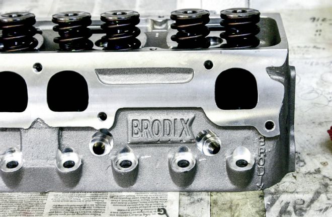 We utilized Brodix aluminum heads and matching intake manifold that fit together perfectly. These heads are the 18-degree design and ones that Dick Anderson personally wanted to try out. ARP fasteners kits were used to bolt all of the parts together.
There is a little mixing and matching of bearing halves that must be done to ensure proper clearance between the bearings and the crank. The same goes for the rod bearing clearances and piston assembly weight matching.
Once we know the clearances are correct and the parts are balanced for weight, we need to check the Brodix head. First we check the head volume. For our motor, we needed to have a volume of 64 cc. It was larger than that and the heads needed to be milled down to that volume. Again, a good machine shop could do this for you.
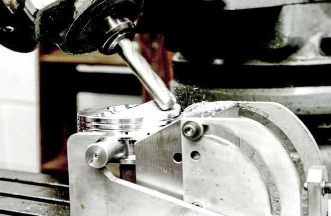 The pistons needed to be cut for relief in the spark plug area. Byron Jr. did the work on the Koury Bridgeport milling machine. This takes quite a bit of experience and skill and should best be left to a professional. Again, we are doing a custom build for this motor that is different than our previous installations where we were using matched parts that you could assemble.
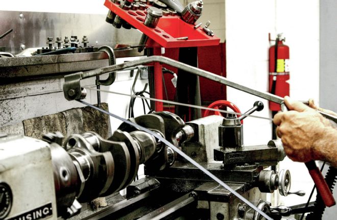 The crank journals are polished by Byron as are all cranks that come through this engine shop. There is a lot of attention to detail at Koury’s and each piece of the motor and each phase of assembly is performed with a lot of care and precision. But that’s what you would expect from a professional who has as many short track wins and championships as Byron and crew have had over the past years.
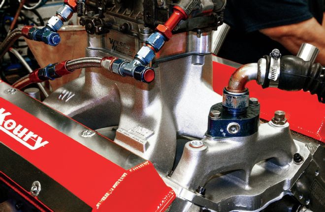 The matching Brodix heads and intake manifold fit together perfectly and needed no massaging, unlike other parts of a build. The 18-degree design is not common with these motors and the parts were somewhat hard to find, but the results would speak for themselves. This particular combination of crank, pistons and rings, block, and heads worked out perfectly.
Once the volume is correct for your application, you need to check the piston to head clearances. For this motor, the pistons were ones that fit the 18-degree head, but were not intended to match perfectly and had to be relieved as to the spark plug position and valve clearances. Again, this was done with a Bridgeport milling machine that takes a lot of talent and experience to operate successfully. Byron Koury Jr. has all of that.
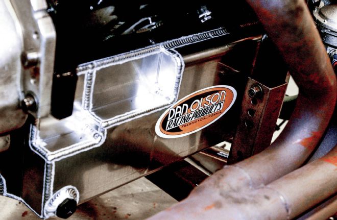 The Dan Olson 10-quart oil pan on this wet sump motor is one that Byron prefers over other makes. It was very well made and fit the block without modification. The break-in oil will remain in the motor through the first race and then it will be analyzed and replaced.
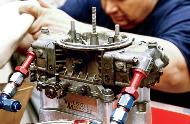 We used Anderson’s carburetor. Normally, Byron will use the shop carburetor first to ensure proper jetting and fuel to air mixture. But this carb has been raced here in Florida before and is very close on jetting.
We also must do the Play-Doh valve clearance check and might need to further cut and relieve the pistons to allow proper gap from the face of the valves to the top of the piston and from the edge of the valve to the edge of the valve relief in the piston. Further milling might need to be done in this area.
Now that the pistons fit, we weigh the piston assemblies and match them to one another. This process had to wait until the pistons were cut to fit because that process might have changed the weights differently for each piston. The lightest piston assembly will be noted and the other heavier pistons will be reduced in weight to match that lightest one.
The rest of the assembly is standard procedure for torquing the crank, installing and degreeing the cam, sizing the rings, installing the pistons and rods, installing the heads, checking the valvetrain angles, and lashing the valves. Again, this is all standard assembly routine that we covered in the first two installments.
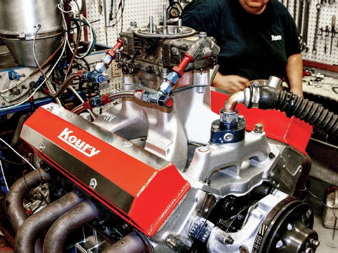
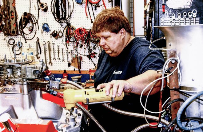
Our next step is to put the engine on the dyno and fine-tune the advance, carburetor, and other settings to find the best power. On the day of the dyno run, I observed the complete motor on the dyno stand. It was impressive. The Brodix heads with matching Brodix intake manifold fit perfectly and the COMP Cams valvetrain set was ready for action.
First we run the motor to make sure there are no leaks, and then run it for a break-in period at about approximately 2,500 rpm before the first dyno run. The engine is filled with specially formulated break-in oil poured into the amazing Dan Olson Racing Products 10-quart aluminum oil pan that Byron prefers. That same oil will stay in the motor until after the first race. Then it will be replaced and the oil filter analyzed. For now, we are anxious to see how much power we have.
The Koury dyno setup is straight up, meaning that all of the correct settings have been set for true atmospheric conditions and other factors. There are settings on dynos where you can trick the dyno and have it put out power numbers that are not real, not that any reputable engine builders would do such a thing.
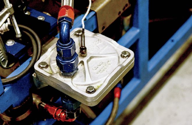 The Oberg filter that is a part of the dyno equipment is checked for any unusual pieces after the initial dyno runs. We saw nothing that would raise any alarms and continued the dyno runs and tuning. This can be the first indication of problems in your motor and we encourage all racers to have their oil filters analyzed on a regular basis to avoid catastrophic failures. If a part is wearing in an unusual way, before it can cause further damage, you can easily detect the problem through oil and filter analysis.
 The dyno in Koury’s shop uses a temperature-controlled water system that automatically introduces cooler water should the temperature rise above a preset level, helping to maintain a set temperature that keeps the dyno runs consistent.
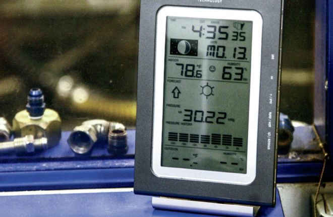 Another part of keeping the test runs consistent is monitoring the atmospheric conditions in the dyno room and adjusting the dyno control center so that the power numbers are based on the exact same conditions of air pressure, temperature, and humidity. All of those affect engine power. You would do well to have your own weather station in your race day trailer. You may need to re-jet your carburetor if the conditions change as to the three mentioned above.
The other features of this dyno are a temperature-controlled water circulating system, exhaust temperature sensors for each header, all of the usual sensors, including oil and water pressure, oil and water temperature, and a high output exhaust fan to vent heat and leaked exhaust gases out and away from the intake.
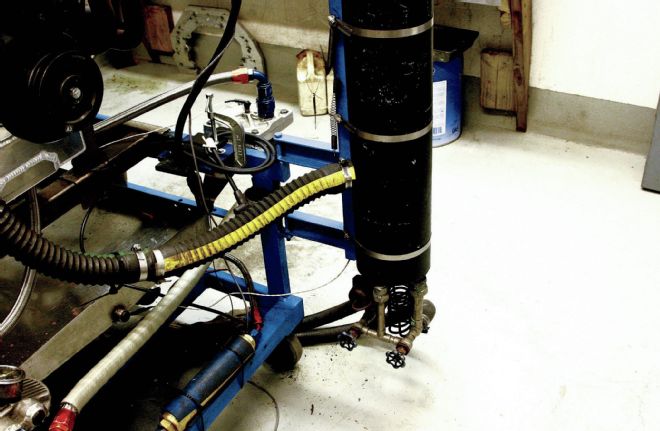
The engine is primed to bring up the oil pressure and circulate oil throughout the engine before final installation of the distributor. Then the plug wires and everything else is attached to the motor, the dyno systems are turned on, and the engine is started for the first time. We immediately checked the block for leaks and there were no serious problems.
The engine is run for a period of time to allow initial break-in and mating of the parts, shut down and then rechecked for leaks or other obvious problems. Then the real dyno work begins. After this initial break-in run, the Oberg filter is opened and checked. Everything looked OK and we proceeded to the next stage.
 Here we see David Thorne prime the motor through the distributor shaft and oil pressure will be observed well before cranking the engine the first time. We then install the distributor, plug wires, and all other connections prior to firing the motor. Koury utilizes many sensors and method of monitoring the motors functions throughout the break-in period and subsequent dyno runs and tuning process.
After the initial pulls, I looked over the torque and horsepower numbers and was very impressed. I won’t give out actual numbers, Byron never does, but the power was very good and the curves very flat, meaning that this motor will pull well throughout the acceleration rpm range. For this type of motor, of which the Kourys have built plenty, these were among the best they have seen for power and consistency.
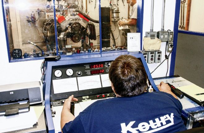 Thorne starts the motor, lets it run for a specified period of time for proper break-in, and then makes the first dyno pulls. Even before adjusting the timing, carburetor jetting, and so on, the motor was putting out impressive torque and horsepower numbers. Byron never releases those numbers, but through many years of experience and building similar motors, he knows what each motor should put out in power.
For example, the power at 5,500 rpm was just 10 hp below what was recorded at 6,200 rpm, and at 6,800 rpm where the curve should be falling off significantly, the power was only about 8 hp below maximum. From 5,800 rpm through to 6,600 rpm, the power never deviated more than 5 or 6 hp. That is all of the way down the straightaway.
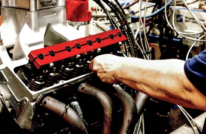 Once we had pulled several dyno runs, Thorne checks the valve clearances and they were perfect and did not need re-setting. The valve covers did require some work to fix a leaking problem. At high rpm, oil would spit out of the breathers and onto the header creating a puff of smoke. It was more annoying than serious, but after installing the Koury design of a breather tube, the problem went away.
I’ve seen plenty of power curve charts and out of all of those, I’ve never seen such a flat curve before, especially with very good power numbers. This kind of consistency is what teams search for. Somehow, the guys at Koury have found the right combination of build parts and processes to achieve this.
The timing started out at 32 degrees Before Top Dead Center (BTDC) and that is the usual starting point for heads with dome pistons. David Thorne sat at the dyno controls and Byron Sr. advanced the timing 1 degree at a time until maximum power was recorded at 35 degrees BTDC.
 The timing could be observed from the dyno control area due to the excellent timing light station developed by Daytona Sensors. Byron utilizes many of the ignition systems developed by DS on his dyno and motors where the client does not specify differently.
The next step is to tune the carburetor supplied by Dick Anderson to find the correct fuel to air mixture that will again provide more efficient combustion and more power while not being too lean for the sake of engine life. We all agreed that this carb was probably very close to the right jetting, having been raced before on similar motors, but this is all part of the fine-tuning.
In between the final dyno runs, the valve clearance was checked and no changes were needed. The crew did have to mess with the valve covers supplied by Anderson and they eventually modified them to their own design of breather tube, which eliminated the oil leakage they had seen at the upper ranges of rpm.
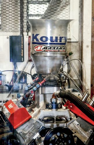 The air that flows through the motor is controlled as to temperature and quality. Note the large fan opening behind the air stack. This pulls a high volume of air through the dyno room, helping to keep heated air and carbon monoxide from entering the carburetor. Everything went as planned and we were all very happy with the results. Now off to the testing phase and on to our first race.
Anderson will be coming over and picking up the motor, installing it in the Circle Track Modified over the next week or so, and then going testing. We’ll be there offering a short review of how it all went. Then it’s on to full-time racing with Anderson behind the wheel of his personally prepared and set up Florida Modified. Stay tuned for the results.