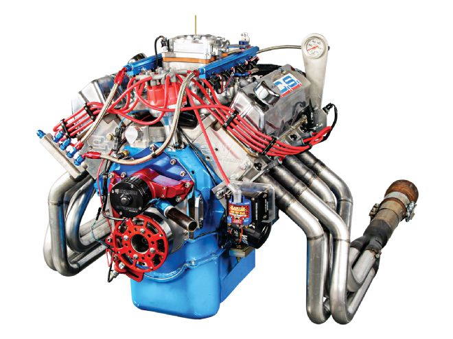
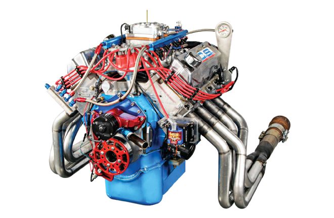
In its OEM form, Ford’s 1970–1974 351ci Cleveland small-block could be considered a case of “too much, too late.” Starting with the basic architecture of the Windsor small-block, the Cleveland was built with a unique 9.206-inch-deck-height block and cylinder heads that used a canted-valve layout. This head design minimizes valve shrouding and unlocks the space for massive valves. Ford produced Cleveland heads in small-port, small-valve versions for 2-bbl applications and in big-port, big-valve configuration for 4-bbl engines.
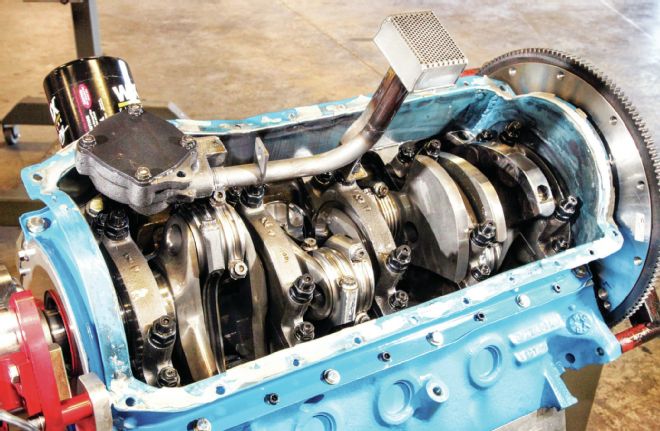 A standard SpeedPro oil pump supplies AMSOIL 10W-40 oil to the modified lubrication system. Restrictions to the lifters and cam bearings allow more oil to be put to work keeping the 4.25-inch stroke Scat crank and Eagle rods alive.
In 4-bbl form, the Cleveland heads were in a league of their own in comparison to other small-block heads. If there is a flaw in its design, it is the compromised exhaust port, which hooks downward at a steep angle toward a low flange to facilitate exhaust manifold installation in vehicles. Ford built several stout performance 351 Cleveland engine packages over the years. However, the insane airflow potential was all but lost in production-car applications that simply could not take advantage of what the Cleveland had to give. When tightening emission standards came into play during the early 1970s, the Cleveland’s fate was sealed.
In the upper ranks of Pro Stock drag racing and NASCAR, the Cleveland did get noticed. Here, the tremendous airflow capacity of the cylinder heads ensured the engine’s legacy. Today, the Cleveland lives on through a hardcore base of enthusiasts and enjoys more aftermarket support than ever before. That support is augmented by components from Australia, where the Cleveland remained in production until 1982.
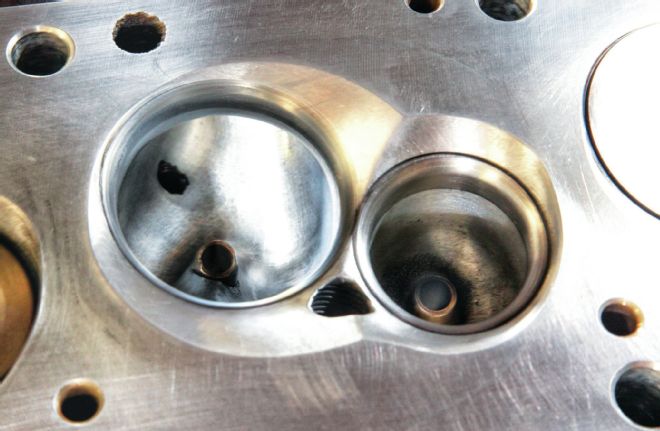 With the valves removed, the port work in the bowl becomes evident. Peak intake flow is reported at 410 cfm, while maintaining a minimum cross-sectional area of 2.3 square inches.
When Ron Stanislawczyk of RCS Racing Engines was contemplating building an engine to compete in the annual AMSOIL Engine Masters Challenge (EMC), the Cleveland seemed to be the right choice. “The availability of the parts is what separates one combustion engine from another,” Ron says. “When I looked at the Cleveland, my thoughts were the CHI heads out of Australia are probably the best head available for a 4-inch-bore engine in this competition.”
Building The Bottom End
Many Cleveland engines are built using Windsor blocks. For the EMC competition, such hybrids were not allowed: “As you know, the Cleveland isn’t known to have a strong block,” Ron says. “We ended up finding a 1971 four-bolt-main 351 Cobra Jet block. We ultrasonic tested all of the cylinders and found it to be pretty solid. Our biggest concern was the front main failing, which can be a problem, but correctly balancing the engine is where we put our major emphasis. We put most of the weight as close to the crankshaft’s centerline as possible. The idea is to reduce the pendulum effect of the large counterweights, which loads the lower bearing shells. With the Cleveland having weak mains to start with, you just can’t afford unnecessary strain.”
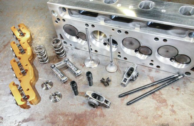 High-rpm performance with a fast-acting, high-lift, hydraulic-roller cam is possible, and Ron’s combination includes Morel lifters, Smith Brothers 0.116-wall pushrods, Manley valves, springs and hardware, Crower steel rockers, and a Jomar stud girdle to aid stability.
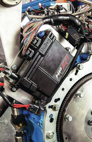 Holley EFI takes control of the spark timing and fuel-delivery functions.
Ron continued with modifications to the oiling circuit: “We bushed the lifter bores, and though the oil passages to the lifters are positioned to constantly feed the valvetrain, we restricted them to 0.060 inch. We also restricted the oil feeds to the cam journals. We used a standard-flow oil pump and shimmed the relief spring 0.125 inch. With the restrictions in the lifters and cam journals, it has very high oil pressure during engine startup and a maximum of 80 to 85 psi oil pressure after three minutes of run time. The bearings in the motor looked absolutely beautiful when we tore it down.”
Filling the block is a custom stroker combination featuring a modified Scat 4.250-inch stroke crankshaft, Eagle 6.00-inch H-beam rods, and custom JE pistons. “We used 6.00-inch Eagle H-beam rods with a 2.100-inch pin,” Ron says. “We considered reducing the pin diameter to 2.00 inch, but our particular crankshaft was relieved in the crankpin area, and we were concerned about breakage with the amount of torque this engine would produce, so we left the pins at 2.100 inch.”
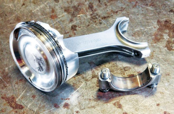 Eagle 6.00-inch H-beam rods are mated to custom JE dished pistons. The ring package features 1.2mm and 1.5mm compression rings and a 2.5mm oil assembly. Ron advises that ring seal should not be sacrificed in trying to minimize ring friction.
The pistons were built by JE with a 1.195-inch compression height and weigh about 360 grams. The pistons have a full-dish crown to get the compression ratio at the 11.5:1 limit of the rules. “Under the circumstances, we couldn’t create enough dish and retain full quench pads on the pistons because we are at 432 cubes and only have 37.5 cc in the combustion chambers. You might ask, why so small on the combustion chambers? Well, the combustion chambers are a by-product of the ports and bore size, and the ports actually continue past the valve and into the combustion chamber. The chamber is the way it is because that’s the way the ports want it to be. There was no room to lower the center of the piston and bring the quench pads in. Either you have quench or you don’t, and they both work fine, but if you are in that gray area from 0.075- to 0.090-inch piston-to-head clearance, we find that to be a detonation problem area—and where you get into trouble.”
The ring package is also from JE, featuring a steel 1.2mm top ring, a Napier-faced 1.5mm second ring, and a 2.5mm oil ring assembly. Compared to the factory stuff from the 1970s, this is a very low drag package, although Ron cautions that you can go too far: “I personally feel low drag on rings is just a matter of a couple of horsepower; I would rather keep the ring seal. In an engine like this, we have a short rod ratio and a piston with a lot of rock in it, so we run pretty stiff radial tension.”
Vital Specifications
432ci Ford Cleveland
Team leader and members Ron Stanislawczyk, Ron Stanislawczyk II, Jon McDonald, Ron Welsh, and Chuck Mazzarese Engine type Ford Cleveland Claimed displacement 432 ci Block Ford Cleveland Bore x stroke 4.0215 x 4.2500 in Compression ratio 11.48:1 Compression height 1.070 in Crankshaft Scat Engine bearings Speed-Pro Connecting rod Eagle, 6.000 in Connecting rod bearings Speed-Pro Pistons and rings JE Pistons Compression and second ring 1.2mm / 1.5mm Camshaft Bullet Cams Cam duration at 0.050 247/251 deg Valve lift 0.825/0.825 in Head gasket Cometic, 0.056-in thick Cylinder heads CHI Valves (intake / exhaust) 2.200 in / 1.600 in Valve lifters Morel Pushrods Smith Bros. Rocker arms Crower, 2.1:1 Engine gasket set Fel-Pro, Cometic Intake manifold CHI Efi ecu Holley HP Throttle-body Aeroflow Ignition system MSD Performance Spark plugs and wires Autolite, MSD Performance Fasteners ARP Flywheel Hays Engine damper Pioneer Water pump Meziere Headers Summit Racing/RCS Valve covers ProForm Hoses and fittings Aeroquip Amsoil oil viscosity 10W-40 Oil pump Speed-Pro Oil pan Kevko Racing Mufflers Flowmaster
Power Parts
Although the CHI cylinder heads were one of the major factors driving this engine build, Ron’s plan from the beginning was to develop his own port design. “We purchased the heads in a raw, as-cast state, which means they come with the ports in a very small unfinished form. The port development started with the intake, then the exhaust, and then the chamber. From there, we digitized the shape and CNC machined the castings. The intake ports flow 410 cfm right at 0.800-inch lift. We are happy with the low-lift flow of the exhaust in the 0.200- to 0.400-inch lift range, where it flowed 270 cfm at its peak. The head has a very small minimum cross-sectional area at 2.3 square inches, and our airspeed is 450 feet per second. You only have so much time to get the air to move, and you need air velocity to move it. If you don’t have 400 feet per second minimum at 28 inches of water [depression], you are never going to get the air to move, especially at lower rpm.”
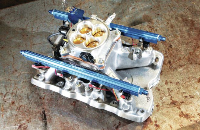 CHI’s 3V single-plane intake manifold routes the air to the heads. Ron installed the injection hardware, but relates that a dedicated EFI manifold configuration such as those designed for modern engines offer a far superior layout.
Besides working to maximize the port efficiency for high flow with a minimal cross-section, Ron emphasizes the importance of keeping cylinder-to-cylinder flow as equal as possible. While the heads have the advantage of eight identical CNC-machined runners, the intake manifold presents different challenges.
The single-plane, 4-bbl manifold was modified for Holley EFI, but it came with compromises, as Ron explains: “With modern engines and EFI there are much better manifolds available, with a full-length plenum feeding straight runners. That’s today’s technology, and I knew the manifold would hurt us with this engine. There was probably a 7 percent flow variation between the manifold runners when we got it, and we closed that up to within 1⁄2 percent.”
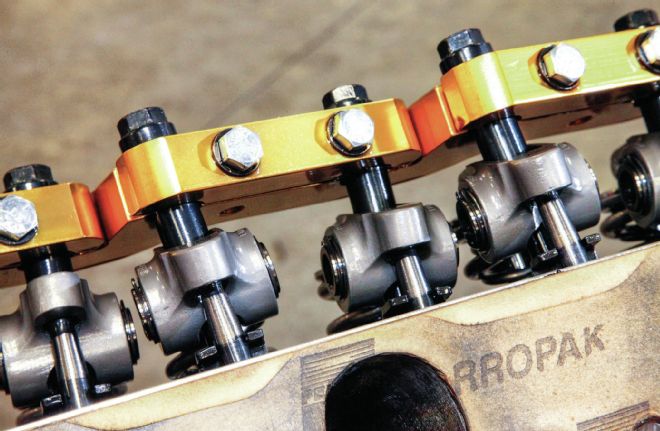 Pumping up the delivered lift are very high-ratio Crower rockers, multiplying the lobe lift by a factor of 2.1:1. The intake rockers are made with a 0.090-inch offset, improving pushrod clearance.
The rules of the EMC require a hydraulic-roller cam. Ron had Bullet Cams grind a custom stick, with specifications of 247/251 degrees duration on a 110-degree lobe-separation angle. The cam delivers a massive 0.825-inch lift through a set of 2.1:1 Crower rockers. Morel hydraulic-roller lifters follow the cam, while thick-wall Smith Brothers pushrods transfer the motion. “I have been building engines for 30 years, and I pretty much know what I need for duration to make a given powerband. The camshaft might be a little small, but with fast ramps and the high rocker ratio, you are opening the valves very quickly,” Ron says.
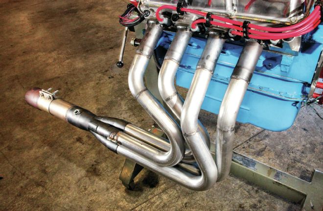 The headers were fabricated using 2.0-inch primary tubes and mated to 3.5-inch merge collectors.
The exhaust side completes the flow system, and Ron admits more development could have led to more horsepower: “For the headers, I just bought a Summit Racing kit and a set of merge collectors and welded them together. There was very little experimentation with the header configuration, and there’s power to be found there—we just didn’t have the development time to pursue it.”
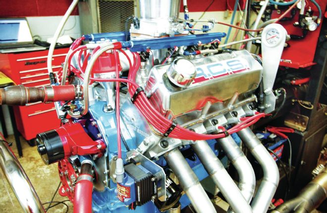 On the dyno at the 2013 AMSOIL Engine Masters Challenge, this Cleveland produced outstanding power, twisting 657 lb-ft of torque and pulling to 747 hp at 6,500 rpm.
On The Dyno
Ford’s best 351 Cleveland engine was rated at 330 hp, but at the 2013 AMSOIL Engine Masters Challenge, RCS Racing Engines’ Cleveland had a chance to show what an extra 81 ci and 45 years of performance parts development are worth. Its 432 spun the dyno relentlessly to a peak of 747 hp at 6,500 rpm and 657 lb-ft at 5,200 rpm. That’s 1.73 hp and1.52 lb-ft per cubic inch—the realm of high-compression, solid-roller, full-on race engines.
On The Dyno
432ci Ford Cleveland
RPM TQ HP 3,000 434.1 247.9 3,100 441.1 260.4 3,200 465.5 283.6 3,300 484.4 304.4 3,400 507.9 328.8 3,500 525.7 350.3 3,600 542.2 371.6 3,700 553.6 390.0 3,800 565.9 409.4 3,900 576.3 427.9 4,000 583.9 444.7 4,100 595.3 464.7 4,200 607.7 486.0 4,300 617.0 505.2 4,400 625.8 524.3 4,500 632.2 541.7 4,600 638.7 559.4 4,700 644.8 577.0 4,800 649.1 593.2 4,900 651.0 607.4 5,000 654.0 622.6 5,100 655.3 636.3 5,200 657.0 650.1 5,300 656.1 662.1 5,400 654.0 672.4 5,500 651.8 682.6 5,600 649.2 692.2 5,700 646.4 701.5 5,800 644.3 711.5 5,900 640.8 719.8 6,000 637.1 727.8 6,100 632.6 734.8 6,200 626.9 740.1 6,300 619.9 743.6 6,400 613.1 747.1 6,500 603.9 747.4 6,600 594.1 746.7 6,700 584.0 745.0 6,800 572.6 741.4 6,900 561.3 737.5 7,000 551.3 734.8
Many say that the short-lived Cleveland architecture was Ford’s finest V8 engine design. The essential layout of the cylinder heads’ canted-valve arrangement is still the basis for the most exotic two-valve race heads of the modern era. If successes were measured by power potential rather than OEM production numbers, the Cleveland ranks amongst the greats.
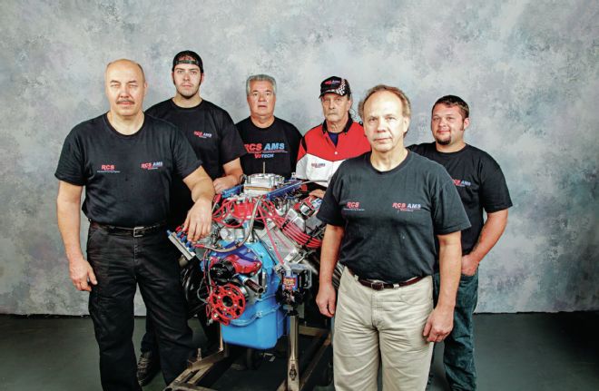 These guys from RCS Racing Engines and AMS Votech had to feel a sense of accomplishment from this engine’s performance. Pictured are Ron Stanislawczyk, Ron Stanislawczyk II, Ron Welsh, Jon McDonald, Chuck Mazzarese, and Robert Goller.