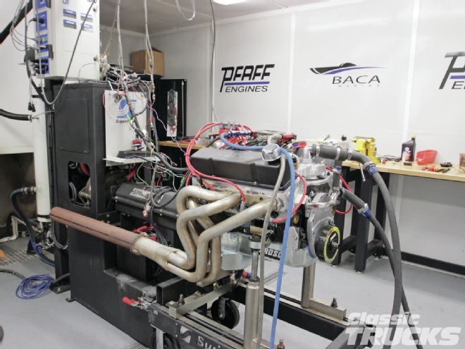
Last month we showed you guys how to machine and properly build a 383 small-block bottom end. We used a Lunati 383 stroker kit with 6.0 rods, -4.9cc flat-top pistons, and performed the machine work at Pfaff Engines. The bottom end was installed and parts were on order for the top end. We decided to use slightly larger heads for our test engine from 180cc to 195cc from Airflow Research (AFR) to increase the upper rpm horsepower while maintaining great lower end torque.
To help control the oil we installed a Moroso oil pan and pump that has oil traps when under hard acceleration, braking, and cornering. The Comp Cams cam was quite unique because it featured a four-grind pattern that helped the intake and exhaust flow better by increasing the duration and lift on the outer cylinders 1, 2, 7, and 8. Comp Cams also increased the exhaust lift and duration on the exhaust side 1, 2, 7, and 8 to promote increased exhaust flow. The cam grind we chose for our 383 build was measured at duration @ .050 230/240, valve lift .620/.608 with 1.6 rockers on a 110.5 lobe separation angle. For the inner cylinders (3, 4, 5, 6) duration @ .050 228/238, valve lift .617/.605, and 109.5 LSA.
One important thing is that the Lunati 383 stroker with the longer H-beam rods needs to have a small base circle cam so that the rods don't hit the cam. The Comp Cams Pro Magnum 1.6 full roller rockers work great to free up engine friction and are very strong and lightweight. Comp claims the rocker arms actually weigh 5 percent less at the valve than comparable aluminum rockers. With a lighter valvetrain, (rockers, titanium spring retainers, valves, etc.) the engine can spin up faster and usually have a higher rpm range, thus making more power.
The intake we chose for testing was a new Edelbrock 7501 RPM Air-Gap for great performance from 1,500-6,500 rpm. This intake is a great choice for truck guys because the Air-Gap separates the oil from the lifter valley area from hitting the bottom of the intake, heating up the intake charge. The cooler intake charge means the engine usually increases performance. We chose to reinstall our F.A.S.T. fuel injection for two reasons: one, it works great to control fuel when driving normally or racing, and two, it self learns. How can we go wrong?
Now it's time to put it all together and walk you through the steps we took to make sure the 383 ran its best.
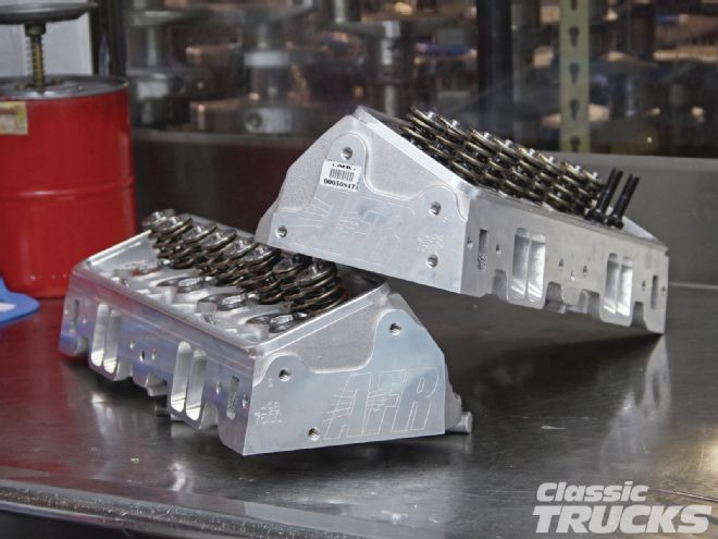 01. Let's start with the 195cc AFR heads that began life with a 75cc combustion chamber, but were milled to 69cc per our request at AFR. Taking material off the bottom of the heads increases the compression ratio.
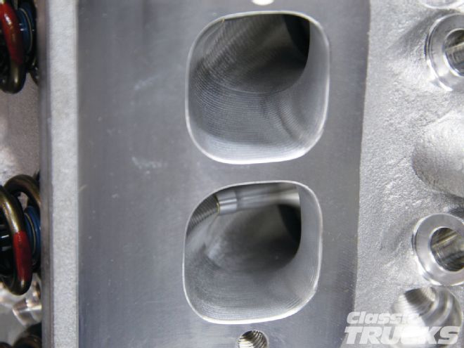 02. AFR uses a five-axes CNC machine that is programed to machine the intake and exhaust runners per AFR's desired dimensions.
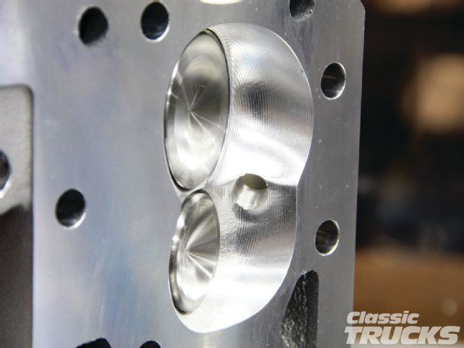 03. AFR also CNC's the combustion chambers and the area behind the valves to promote increased engine flow characteristics.
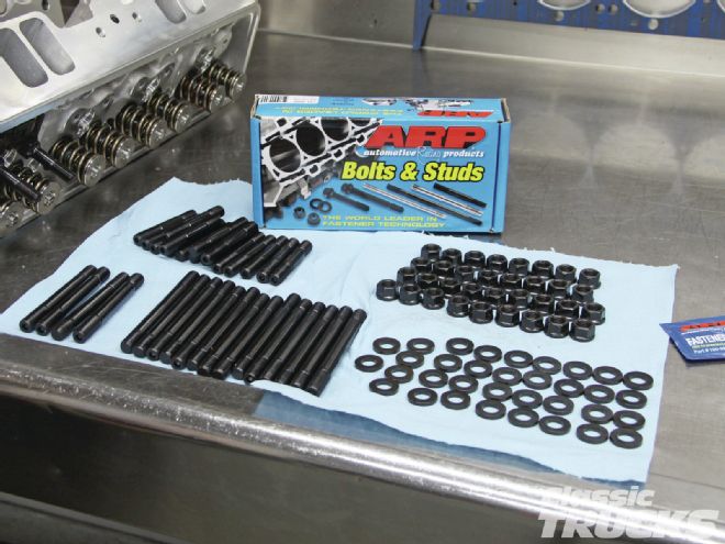 04. We used ARP head studs to hold down the heads to the engine block. Make sure to use a thread chaser and not a tap to clean out the head boltholes.
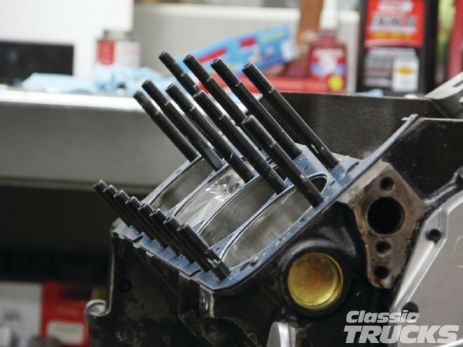 05 A .051 thick 1044 Fel-Pro head gasket was used to get the compression ratio of 10.3:1. This will give us plenty of throttle response because of the increased compression, but save the hassle of having to purchase expensive fuel additive needed by higher compression engines. Our test engine used -4.9cc pistons that were +0.10 out of the hole. Combine that with our 69cc AFR heads and the 0.051 head gasket we were right on target with squish and quench of 0.041. Make sure to use plenty of ARP white thread sealer on the head studs or bolts and Gordy recommends Gasgacinch on the both sides of the head gasket.
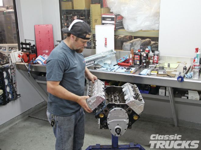 06. Gordy Jennings from Pfaff Engines in Huntington Beach, California, made sure my valve-to-piston clearance was OK. He measured the intake and exhaust valves to the piston clearance at the valves at full lift on the cam. After Gordy made sure the piston had enough clearance we bolted on the heads.
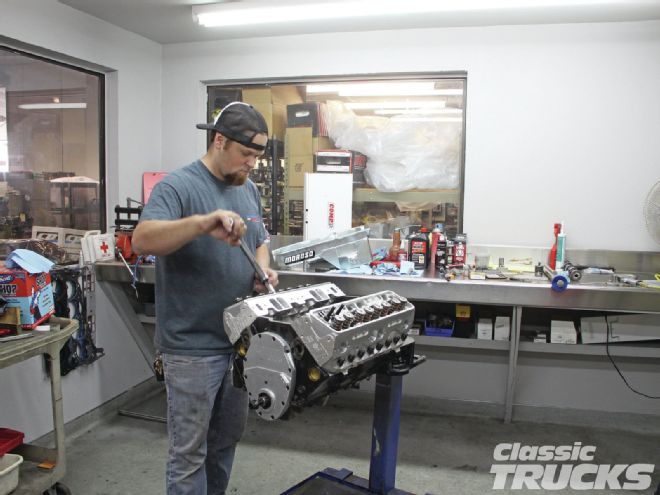 07. Head bolts were torqued down in sequence per the GM manual. Since we are using ARP studs they recommended tightening the head bolts in 10 lb-ft increments starting at 40 lb-ft and working all the way up to the recommended 80 lb-ft for ARP studs and 70 lb-ft for ARP bolts.
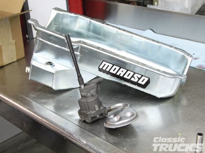 08. We used a Moroso road race oil pan to control oiling during acceleration, braking, and cornering.
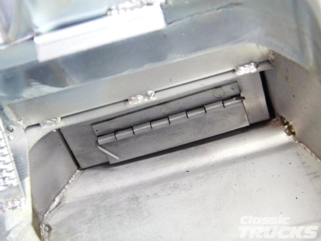 09. This is an oil scraper that helps remove oil from the crankshaft while the crankshaft rotates.
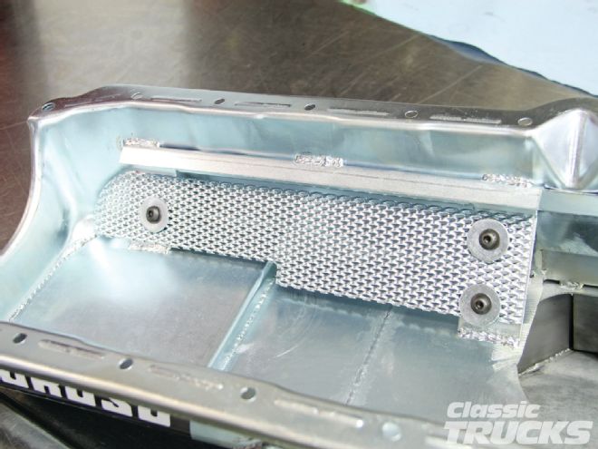 10. The Moroso pan has a baffles down low that either trap or let oil flow to the oil pickup.
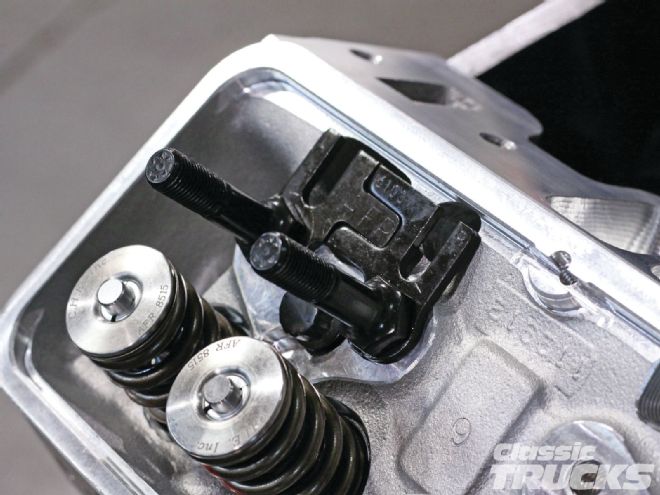 11. Back to the top end. One important step is to make sure the pushrods are the correct length. To check pushrod length you need an old pushrod or a Comp Cams adjustable pushrod. First step is to install the AFR adjustable guild plates, but don't tighten them down yet.
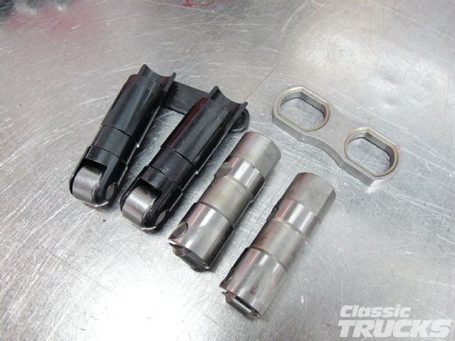 12. For lifters we are using Comp Cams short-travel hydraulic roller lifters with link bars. The Comp lifters shown on the right have no lifter bar and are regular travel with a stock Gen II style lifter guild. The reason we wanted to go with short-travel lifters is that they generally can take the higher rpm's without pumping up the lifter causing improper valve adjustment. The short lifters are a great addition to anyone who wants to autocross, drag race, etc., without having to go with a solid hydraulic roller lifter.
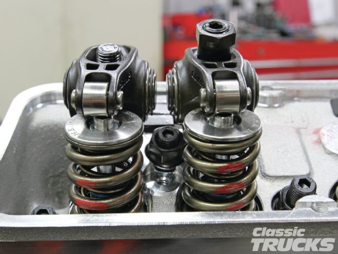 13. We used Comp Cams Pro Magnum Full Roller Rockers for the top end. Notice that the left rocker is not adjusted properly on the top of the valve. The AFR adjustable pushrod guides need to be moved and torqued to make sure the rocker tip is centered side to side over the valve. This way the rocker can push down on the valve and not try to bend it left or right causing bind.
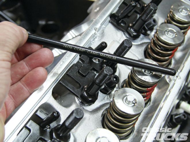 14. We ended up using Comp Cams pushrods (part number 7609) that are 5⁄16 .080 thick. These Comp pushrods are 7.3 inches long and are made of C1020 high-carbon chromoly. Did you happen to notice that we added the titanium spring retainers to reduce valvetrain weight? The titanium spring retainers help reduce valve float at higher engine rpm's that will rob the engine of power.
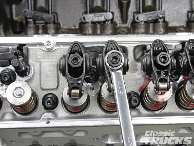 15. To adjust the Comp rockers I suggest you use the locking type rocker nuts; this way they will not back out. I made sure the cam was off the lift and adjusted the pushrod to zero lash.
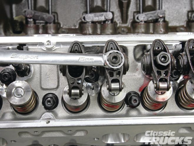 16. Comp recommends a quarter turn clockwise from zero lash for the short-travel lifter. Tighten the locking Allen nut down and rotate the engine by hand and check the contact patch between the top of the valve and the rocker roller tip. If the rocker is pushing on the center of the top of the valve then the pushrod length is correct.
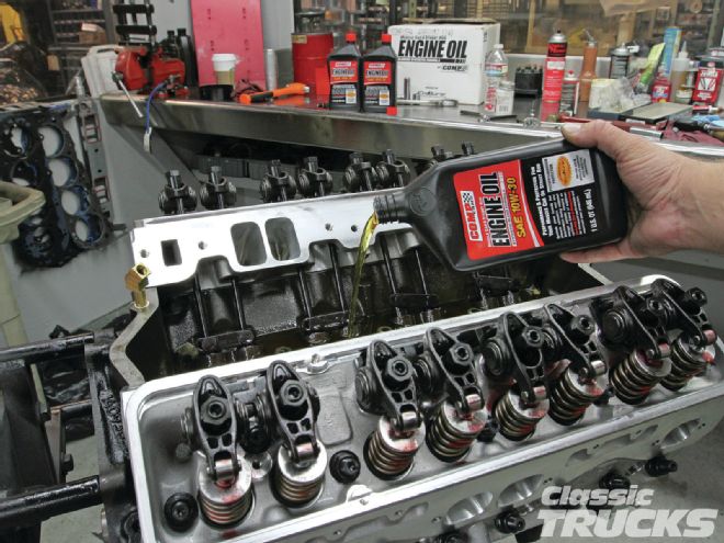 17. With the rockers adjusted we added 5 quarts of Comp Cams 10-30 oil making sure all the lifters were saturated with fluid.
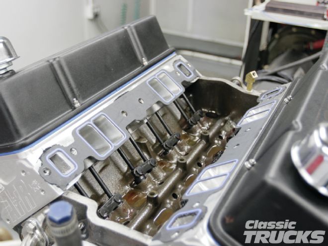 18. All the Fel-Pro gaskets were ordered from Summit Racing where we could view the specs of what size they were. For example, our head gaskets and intake gaskets needed to be within specs so that the heads would perform well. We used 1205 intake gaskets that fit our AFR heads perfect. AFR doesn't recommend port-matching gaskets to the heads because for the most part they have already done the work for you.
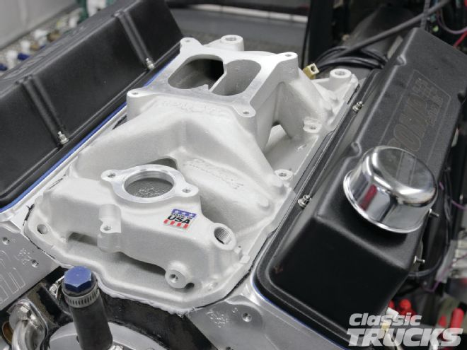 19. An Edelbrock 7501 dual-plane intake manifold was used to get the engine's power where we wanted it for street driving and autocross. This intake provided good torque down low, while having good breathing at higher rpm's. Intakes combined with the correct camshaft can bring new life to an engine that is choked down.
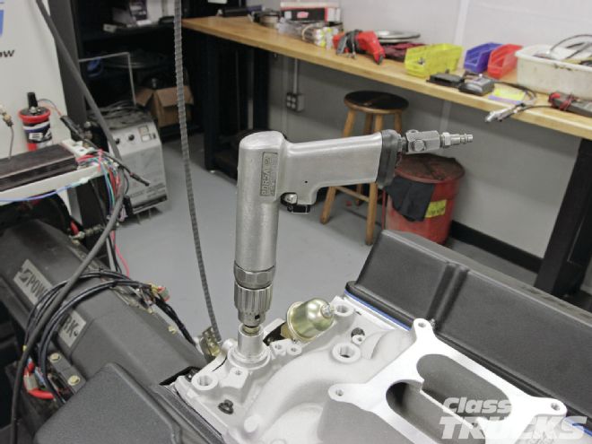 20. With the engine on the dyno we primed the oiling system with a Summit Racing oil pump priming tool. This will ensure that we don't damage the engine during first start-up.
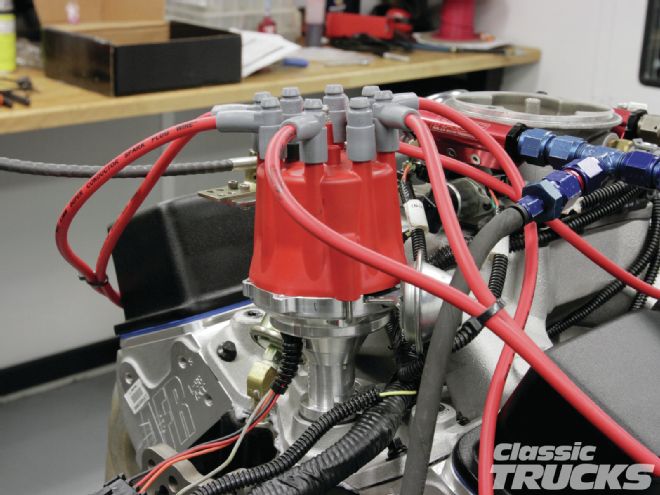 21. We used a Ready-To-Run MSD Pro Billet distributor to control the spark. Timing was set at 18 initial and 35 total for the first few runs. Then we moved it up to 21 initial, 38 total, and the engine liked the change. But we later found out that the cheap distributor hold-down clamp I used was letting the distributor rotate, thus retarding the timing. AFR has tested the 195cc heads on a lot of SBC applications and found that 34-35 degrees total timing is usually where the engine makes best power.
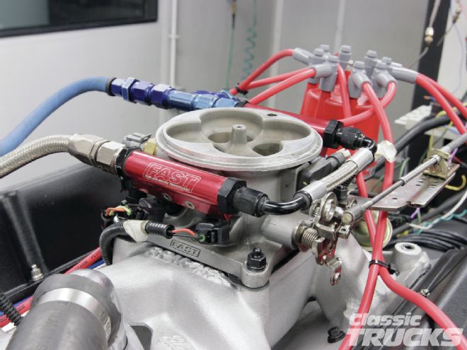 22. I chose to reuse my F.A.S.T. EZ-EFI because it was easy to use and could handle the power that this engine would produce. The fuel pressure was set at 43 psi.
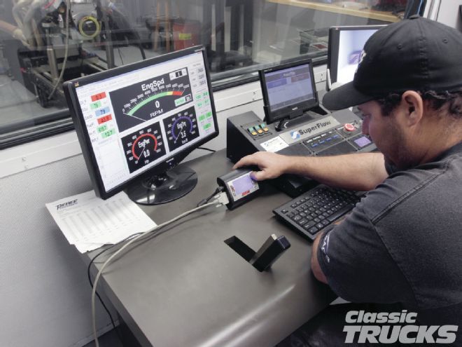 23. With the required sensors hooked up to the dyno and F.A.S.T. computer we were able to start a new program tune with the handheld controller. Here, Joe Baca goes step by step through the control prompts to program the start parameter. The engine was started and run in a preprogramed engine break-in, while Joe watched the O2 sensor readings for safety.
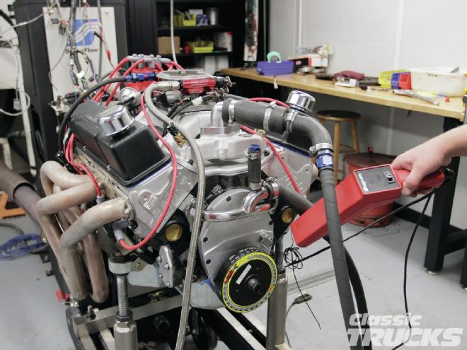 24. The timing was then rechecked and that's when we found out that the hold-down clamp was not holding the timing. Unfortunately we found out after several dyno runs that the distributor was rotating and retarding the timing on us because of the clamp. With a new distributor hold-down clamp we set the timing to 38 degrees total and made some more full dyno runs on the engine.
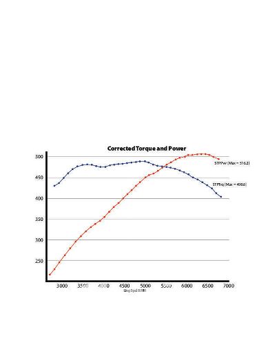 25. The EZ-EFI hasn't fully self-learned yet, but we were still able to make great power and save fuel on the long hauls. Speaking with Tony Mamo, AFR's head of R&D, was also insightful. He mentioned if you wanted to use a carbureted setup on the dual-plane intake then a 950-cfm carb could have made more power and that the engine would have responded favorably to less timing. His testing has found that with their more efficient chamber and port designs, most of the new AFR Eliminator heads make the best power at 34-36 degrees. Unfortunately, we ran out of time on the dyno and never tried anything under 38 degrees. Mamo also added that if you wanted to skew the curve to favor a little more horsepower, running a single-plane intake similar to the AFR Titan TXR could have added more horsepower and extended the curve, albeit at the expense of some bottom end torque. Considering all the areas of improvement we didn't have time to explore, this engine's output is extremely impressive, especially with camshaft s