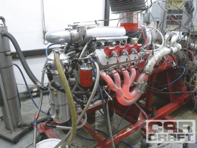
The scene is the local cruise hangout. The hood is open on a young car crafter’s black-primer Pro Street Mustang, and a small group eavesdrops on a deluge of overlapping technical discussions regarding turbos, boost, camshafts, and a dizzying array of other power-related topics. The Mustang driver innocently asks for feedback on his cam selection and is quickly barraged with several contradictory recommendations, each of which are vehemently defended as gospel. The young driver is soon overwhelmed and quickly closes the hood of his car and leaves while a pair of turbo true believers square off in a technical fencing match that looks as if it will devolve into a jihad-like religious riot complete with willing martyrs.
While this scenario might be fictional, the debate is real enough and rages across the Internet in forums and tech chat rooms dedicated to anything related to boost. The problem with opinions is that everybody has one, with few rooted in real-world experience or established combustion theory. So we decided to seek out those who talk less and race more. Our participants include Kenny Duttweiler, who began experimenting with and racing turbo Buick V6 engines virtually from the moment those black sedans hit the showroom. He now builds the maxi-turbo’d, mini displacement, 299ci small-block Chevy powering the George Poteet-driven Speed Liner Bonneville streamliner that blitzed the Salt with a 436-mph exit speed last year. We also talked to street and dragstrip turbo expert Kurt Urban, who lets his 100,000-mile turbocharged street truck speak for his knowledge of how to use boost to become an Urban guerrilla. Then we quizzed our favorite rocket scientist, Comp Cams’ lobe designer Billy Godbold, who lent his insight into eloquently combining cam timing with boost pressure and not getting squeezed in the process.
Turbo Cam Basics
The one thing that all three of our noted sources emphasized is that the knowledge base established from turbochargers designed 10 or 15 years ago is antiquated when applied to the current crop of high-efficiency turbochargers—unless you’re trying to get by on old, cheap turbos. “In the old days it was typical to see 1.5 to 2:1 backpressure ratios,” Duttweiler says. “Today the backpressure is actually less than the boost pressure.” The ratio Duttweiler is talking about is the relationship of exhaust backpressure to inlet boost pressure. Exhaust gas backpressure is naturally created when the hot gas exiting the exhaust ports arrives at the turbocharger’s turbine wheel. The exhaust gas “stacks up” between the exhaust port and the turbine wheel, creating pressure as it would with any restriction. All internal combustion engines perform best when tuned with a certain amount of camshaft overlap in which both the intake and exhaust valves are open at the same time. If the exhaust backpressure is greater than the inlet pressure, the exhaust will push back into the cylinder and (given enough time) up into the inlet manifold. Exhaust gas doesn’t burn a second time, so it works just like an emissions-era exhaust gas recirculation (EGR) system, reducing power, except it’s happening at wide-open throttle (WOT). Because of the high backpressure ratio, older turbos required an earlier-closing exhaust valve, which was most easily achieved with a wider lobe-separation angle (LSA). This could be where the now-common wide-lobe-separation-angle theory propagated. According to Duttweiler, today’s more efficient, larger turbos reduce that backpressure, which minimizes the power-robbing effect of exhaust dilution. That means the LSA can be tightened, which is contrary to the contention that all turbo cams must have wider 112- to 114-degree LSAs. With newer turbos, the reduced backpressure also means the exhaust valve can be opened sooner and held open longer, which is generally accepted as beneficial to high-rpm power production, just like on a normally aspirated engine. According to Duttweiler, to make good power, turbo engine efficiency depends more on low exhaust backpressure than tricks with the cam.
Duttweiler also mentioned that attempting to build a turbocharged engine with a set LSA (such as 112 or 114 degrees) can lead you astray. He mentioned some work he did way back in the early Buick Turbo V6 days while racing these engines in NHRA Stock Eliminator. Stock class rules required the intake and exhaust lift and duration specs to remain stock, so to improve power, he tightened the LSA on these engines to 109 degrees to help the Buick’s really small cam improve power. The engine responded by building boost much quicker. “When you spread the lobe-separation angle way out, the engine gets lazy,” Duttweiler says. As an example of a good V6 engine, Duttweiler says he built a V6 turbo Buick with a 215-degree-at-0.050 intake lobe camshaft that made 900 lb-ft of torque and 580 hp and idled at 16 inches of manifold vacuum. The concept of lobe-separation angle and duration is addressed more fully in the accompanying sidebar “Overlap Chronicles.”
Duttweiler says this idea reinforces the concept that it’s not necessary to use radical lobe designs with turbo engines. “A turbo allows you to run a milder lobe and valvespring package that’s much easier on the engine.” An example of this is a slew of very reliable turbocharged Bonneville engines built by several turbo engine builders, notably Duttweiler and turbo engine guru Mike Lefevers. Often these engines will make multiple 5-mile-long sustained WOT passes and require little more than pulling a spark plug for maintenance. A properly designed valvetrain and a less aggressive lobe design can virtually eliminate valvetrain problems such as broken springs, bent pushrods, and mangled rockers. There are caveats however. Duttweiler and Urban both emphasize that attempting to open the exhaust valve too early can cause bent pushrods. This is mainly due to the surface area of the exhaust valve attempting to open against high cylinder pressures. “You will need bigger pushrods,” Duttweiler warns. “I see more bad things happen on the exhaust side trying to open against cylinder pressure.”
Cylinder head selection also comes into play when selecting a camshaft. Just like with a normally aspirated engine, Duttweiler says a well-flowing cylinder head will allow shorter duration figures to carry the power to higher engine speeds. Less efficient heads do the exact opposite, requiring more duration to compensate for the weak flow. This is reinforced by what we’ve noticed here at Car Craft on our dyno testing of normally aspirated engines. With a given cam timing, adding better heads extends the peak power rpm point, while weaker heads will do just the opposite. But typically there are limitations when dealing with a turbo. Duttweiler warns that a properly designed turbo “will run the engine well past its ability to control the valvetrain and will go right into valve float!” That means valvesprings are just as critical as with normally aspirated engines. This tends to emphasize mechanical roller cams rather than hydraulic rollers, although hydraulic rollers seem to have an edge on durability for street engines.
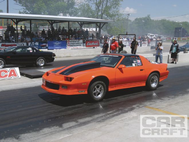 Drag racing is all about the launch and having enough power on the starting line to leave hard. A turbo motor with too much duration or too wide an LSA will make the car soft on the starting line and slow to build boost.
If all this sounds just like what normally aspirated engines want (and it is), then go to the head of the class. Duttweiler says you can and probably should treat a properly sized, high-efficiency turbo motor like a normally aspirated engine. An early-opening exhaust valve can be beneficial for top-end power because even high-efficiency turbos still have to work against some exhaust backpressure. The earlier-opening exhaust helps to reduce residual pressure in the cylinder before the intake valve opens.
Advanced Classes
There’s much more to cam timing selection, however, than simply tightening the LSA when using a more efficient turbocharger. The difficulty in choosing camshaft specs is that much of the advice that comes from professional engine builders is usually aimed at ultimate power applications such as Bonneville or 6-second, 2,400hp drag cars. Expanding on our comparison to normally aspirated engines, you wouldn’t choose the same camshaft for a 500ci NHRA Pro Stocker as you would for a 350ci, 400hp street engine. Given this, there are many factors that go into choosing a camshaft for a street-driven turbocharged engine. Kurt Urban has tons of experience in such things, and he’s used a variety of different cam designs based on how the engine will be used and the car it will power. When it comes to cams Urban says, “For me, it’s what works in the car.”
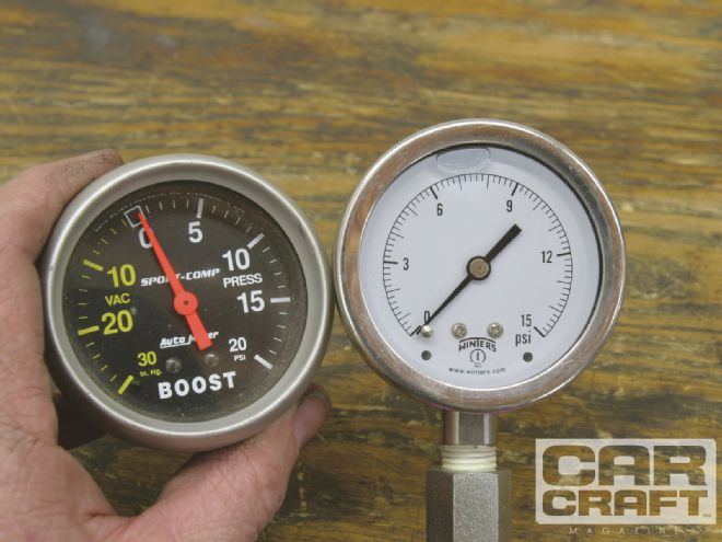 Knowing inlet boost pressure alone is not enough to discover if your turbo engine is running efficiently. To have all the information, you will need a second pressure gauge to monitor exhaust pressure between the turbo and the exhaust port. A good turbo will produce less backpressure than boost. Older, less efficient turbos can experience up to 2:1 exhaust ratios where if boost is 10 psi, the backpressure might measure 15 to 20 psi.
Urban went on to say, “I try to design a cam around what I think the driver needs. Everybody wants big power, but what you really need is a cam that races well.” As an example, Urban says, “With a Powerglide, a big camshaft and a big turbo don’t work well together. The car would be lazy off the line, and the power would only come on hard at the top end.” So in that case, he says a shorter-duration camshaft would probably work better to launch the car because so much of elapsed time is based on starting line acceleration. “In drag racing you want the car to leave, so I take into account what the car weighs, the displacement, how good the driver is, and probably a dozen other details to fit the cam. Sometimes I’ll cam the motor smaller to make the car easier to drive and add duration later as the driver improves.”
As an example, Urban says, “I built an engine for a drag radial car with a 427 LS. The camshaft had the normal split at 260/272 degrees (at 0.050) with a 115 separation angle. The motor used 1,400 pounds of fuel at max power, and the car runs 7.20s at more than 200 mph. At 1,400 pounds per hour—that’s well over 2,000 hp. I tried a 272/280 cam to make more peak power, but the car ran slower because it wouldn’t leave even though it made 5 more pounds of boost at the top.” As both Duttweiler and Urban have emphasized, this is much like a normally aspirated engine in which too much duration killed the bottom-end power and the car ran slower.
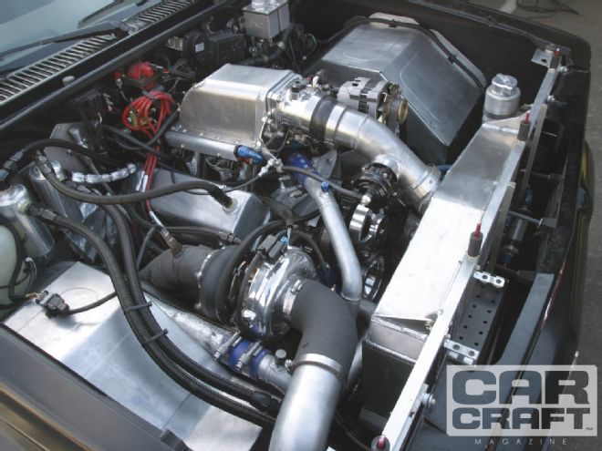 Adam Auerbach built this single-turbocharged Buick V6 Syclone pickup for open road racing but also competed at the 341 Challenge (see Nov. ’10, page 76). Cam timing for a turbocharged road-race engine would be similar to that on a street car, with an emphasis on manageable midrange power.
To emphasize that taking into consideration how the car will be used is critical to camshaft selection, Urban built an engine for a heavy street car that appears to fly in the face of conventional turbo cam wisdom. “I built an LS engine with a 227/223 cam with 0.614/0.610 lift with a 72mm turbo—it makes 900 lb-ft of torque at 3,500 rpm in my all-wheel-drive Chevy truck. It runs 11.40s at 120 mph and I’ve got over 100,000 miles on it!” Here the application demands lots of torque because the engine builder is faced with a very heavy vehicle with a tight torque converter and not much gear ratio to help it get moving. The combination of a short-duration intake lobe with an even shorter-duration exhaust lobe than the intake (sometimes called a reverse split cam) means the cam timing emphasizes low-speed torque as evidenced by the incredible torque at a relatively low engine speed.
Urban went on to say “Turbo engines run faster (at the track) when you open the exhaust valve sooner. With short intake duration, the engine responds with speed at the track. By opening the exhaust valve sooner with either a tighter lobe-separation angle or long exhaust duration, the engine generally responds better. You will lose scavenge if you open the exhaust valve too late.”
Overlap Chronicles
Overlap is defined as the number of crankshaft degrees of rotation established between when the exhaust valve closes (EC) and the intake valve opens (IO). This is established by several factors. We discussed this idea with Comp Cams’ lobe designer Billy Godbold. Godbold says the popular belief is that the lobe-separation angle is responsible for the amount of overlap, but that is only partly true. The important other half of the equation is the length of both intake and exhaust lobe durations. If either intake or exhaust duration increases, it will affect overlap. The accompanying Comp Cams illustration makes this easier to understand. If we move the intake and exhaust centerlines closer together, the angle gets smaller—as from 114 degrees to 110 degrees. When this happens, that small triangle that indicates overlap increases in size.
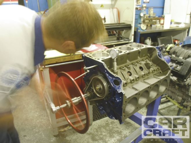 The only way to know if the cam timing is where you want it is to degree the cam. Large-diameter degree wheels are more expensive but are also far more accurate than smaller wheels. End
With a given lobe-separation angle, overlap will increase with added duration. We’ve included a short explanation of how to calculate overlap from the opening and closing points given on the cam card. In our case, the specs for these three Comp cams are offered at 0.006-inch tappet lift. As you can see, increasing the duration from the smallest to the largest cam increases the overlap by an amazing 12 degrees, even though the lobe-separation angle remains at 110 degrees.
How to Calculate Overlap
Comp Cams XR276 HR hydraulic roller cam PN 12-423-8
Duration: 224/230 degrees at 0.050 at 0.006-inch tappet lift
Cam installed at 106-degree intake centerline
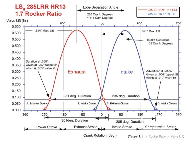 This Comp Cams illustration clearly shows the triangle-shaped overlap area (arrow) that is created with the combination of exhaust closing and intake opening points. As you can see, moving the centerlines closer will increase overlap, while spreading the centerlines farther apart will reduce overlap.
Overlap = Exhaust Closing (EC) + Intake Opening (IO)
Intake events: IO = 32 BTDC; IC = 64 ABDC
Exhaust events: EO = 75 BBDC; EC = 27 ATDC
Overlap = 27 + 32 = 59 degrees Now let’s look at three hydraulic roller camshafts with three different intake and exhaust durations yet with the same lobe-separation angle of 110 degrees. All overlap figures are given at 0.006-inch tappet lift.
Comp XR 270: 218/224 degrees duration at 0.050
Overlap = 24 + 29 = 53 degrees overlap
Comp XR 282: 230/236 degrees of duration at 0.050
Overlap = 30 + 35 = 65 degrees overlap
Comp XR294: 242/248 degrees of duration at 0.050
Overlap = 36 + 41 = 77 degrees overlap
Even though the lobe-separation angle of 110 degrees did not change with these three cams, the overlap increased a total of 24 degrees because both the intake and exhaust durations increased by 12 degrees with each larger cam.