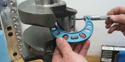
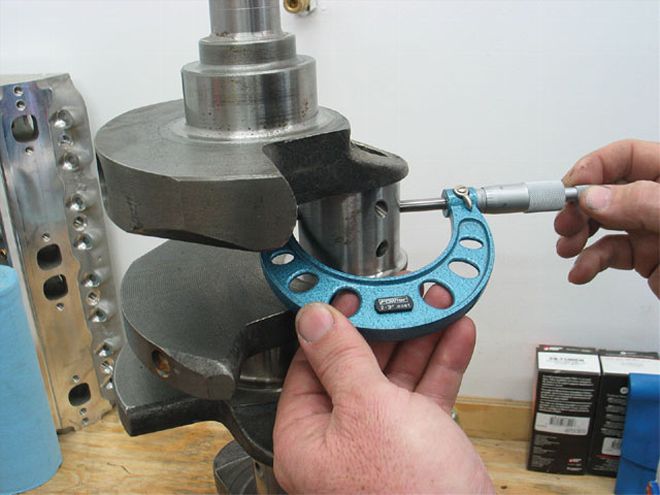
Careful measurement is the key to quality work. Work slowly when measuring rod journal diameter to guarantee an accurate reading by ensuring the micrometer is perpendicular to the journal surface.
If you're one of those guys who take pride in building a high-performance engine, you know that one of the most important aspects of making that rotating mass live a long and powerful life is setting bearing clearances. With more people building killer street engines, we thought it would be a good idea to touch on a few aspects of main- and rod-bearing clearance, how to accurately measure housing bores and crank journals, and easy solutions for too-loose or too-tight clearances.
How To Measure Bearing Clearance
While Plastigage has its supporters, for this exercise we prefer to use a micrometer and a dial bore gauge to accurately measure journals and inside diameters to determine bearing clearance. The most important thing to remember is to always be consistent and measure everything using the same tools the same way. This also applies to temperature. Crankshafts, rods, bearings, and micrometers are all constructed out of varying grades of steel or iron that expands and contracts with temperature. All quality micrometers are designed to be used at a standardized temperature, usually 20 degrees C or 68 degrees F. Since hot parts expand and cold parts contract, it's easy to see how temperature can affect both the steel micrometer and the part you are measuring. even a temperature difference of 10 degrees on either side of this standard can affect accuracy. We did a quick test for rod-bearing clearance between 58 degrees and 72 degrees and discovered that as the tools and parts got warmer, our bearing clearance tightened by 0.0005 inch! Imagine what adifference of 30 degrees (70 to 100 degrees F) would be worth.
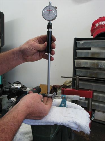
We set up the dial bore gauge by using the same micrometer to set a 2.1000-inch diameter. Some engine builders set the dial bore gauge at the rod journal size and read the actual clearance on the dial indicator. We prefer to set the dial bore gauge at a common journal diameter and do the math. This way, we measure all eight rod bearings' inside diameters with one setting.
We're using a set of Fowler outside micrometers from Precision Measurement Supply along with a dial bore gauge. If you've never used a micrometer, just click on precisionmeasure.com/microm1.htm and this site will run you through the procedure. For our small-block Chevy, we measured a typical rod journal using a Fowler 2- to 3-inch outside micrometer. First, measure the outside diameter of the journal. our rod journal measured 2.0989 inches, which we wrote down. now, using that same micrometer, we set up our dial bore gauge to read 2.1000 inches. Most engine builders skip the step of measuring the housing bore, but it's worth mentioning that most bearing-clearance issues stem from inconsistent housing-bore diameters. All quality rod and main bearings are very close in terms of consistency, but a tolerance stack of a tight housingbore diameter combined with a slightly oversize rod journal can contribute to tighter than acceptable rod-bearing clearance.
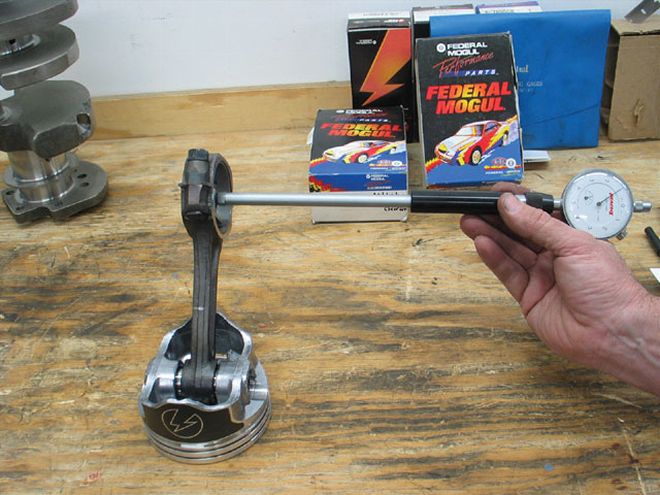
Always measure bearing inside diameter only in the true vertical. All rod and main bearings are designed to increase clearance, approaching the bearing parting line so that the bearing doesn't grab the journal when torqued in place.
After measuring our connecting rod bearing inside diameter at 2.1018 inches, it's a simple procedure to subtract the rod journal outside diameter from the rod bearing inside diameter: 2.1018 - 2.0989 = 0.0029 inch. This means we are just shy of 0.0030 inch of oil clearance for this rod bearing. For some engine builders, this may be acceptable, but others may prefer to have rod-bearing clearance closer to 0.0025 inch, which means we need to tighten the clearance by 0.0004 inch or roughly half a thousandth of an inch. of course, the opposite is also possible, where we have a larger crank journal and a tight rod bearing inside diameter. This might require a full 0.001 inch additional clearance just to get to a minimum clearance, such as 0.0021 inch. Faced with either tight or loose clearances, this is where many entrylevel builders accept the clearance they measure because they don't realize they have options.
Customized Clearances
It's actually very easy to create the bearing clearance you desire. In the above situation, where we have more clearance than we need, many performance bearing manufacturers such as Speed-Pro, Clevite, and ACl (among others) offer both undersize +0.001- inch (X- suffix) and -0.001-inch oversize rod and main bearing shells that can be used to customize clearance. In our small-block Chevy rod-bearing example, we can decrease the clearance by using a half shell of a 0.001- inch undersize bearing pair. This is a perfectly acceptable procedure as long as you are substituting a half shell from the same bearing manufacturer and from the same design series of bearings. For example, Speed-Pro offers competition-series 350ci small-block Chevy rod bearings in standard and 0.001-inch under (-1) and over (1X) sizes.
Mixing one standard half shell and one -1 undersize bearing half should create the bearing clearance we desire. In this case, you would put the thicker half shell in the upper portion of the rod where it can take the additional load. other engine builders claim it really doesn't matter as long as you are consistent. of course, this requires purchasing a second set of rod or main bearings to mix the bearing shells required to create the clearance you want.
Clevite, for example, offers additional bearing-clearance options in the 0.010-undersize arena for the small- and big-block Chevys and other popular engines. The Clevite h-bearing series is now available in -9, -10, and -11 (or 10X), along with -19, -20, -21 bearing bearing sizes in the Clevite high-performance h-bearing family, which means you now have the parts to accurately set bearing clearance even on 0.010- and 0.020- under cranks. So the task of setting your rod and main bearing clearance just got easier. In an election year, who wouldn't vote for that?
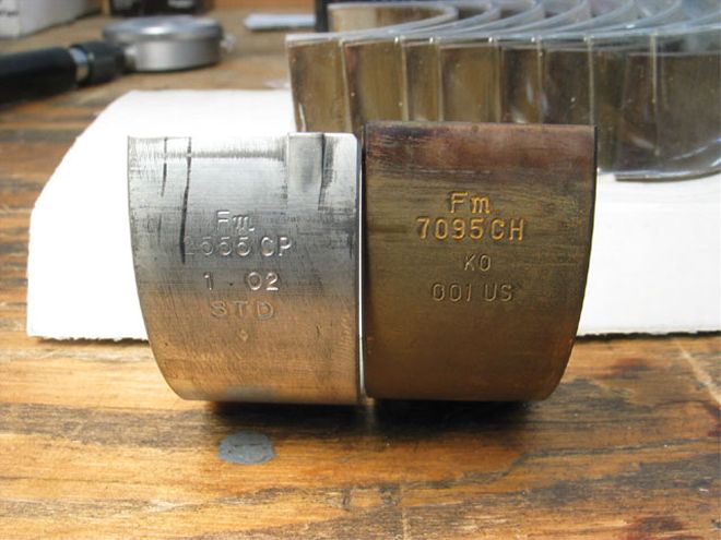
In this photo, the bearing on the left is for a standard journal diameter while the bearing on the right is 0.001 inch undersize (-1). If only one half shell were used, it should theoretically reduce clearance by 0.0005 inch.
Bearing Tips And Tricks
1. Always check your micrometer with a standard before measuring.
2. Always use the same micrometer for the journals and to set the inside mic diameter.
3. Torque the rods and mains to spec before measuring a bearing inside diameter.
4. Changing rod bolts or moving from bolts to studs in the main caps will affect bearing clearance.
5. Temperature will affect the accuracy of the micrometer and the size of journal diameters both inside and out.
6. If you have one tight and one loose rod-bearing combination, try switching the bearings between the two. We've seen this work several times when the clearances are just a little bit off.
7. Never mix different bearing families when customizing bearing clearance. If you are using Federal-Mogul coated bearings, don't mix in a half shell uncoated race bearing.