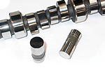
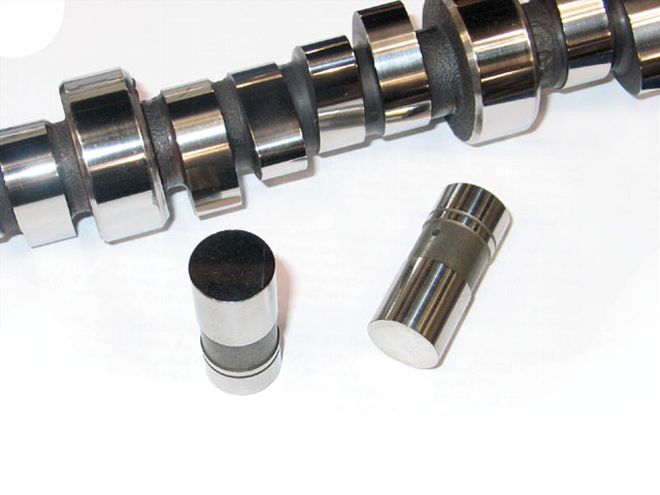
 Don't just depend on catalogs or advertising. Understanding how a cam's design affects performance can help you tune the engine for your car, the track you race, and even the way you like to drive.
For some of us, camshafts are a lot like marriage-we understand the concept but cannot fathom exactly how to make it work. For example, why is duration always measured in crankshaft degrees? And why do you not begin measuring duration until 0.050 inch of lift? Or why do camshaft manufacturers grind a cam advanced? What does the lobe separation angle have to do with performance? And why does advancing the camshaft seem to help low-end torque?
The science behind camshaft design is as advanced as anything in a race car, so most of us-including experienced engine builders-depend on the manufacturer to help spec the right cam for a particular engine package. Still, there is a science that controls every part of the design of your camshaft, and understanding why different parts of the cam are designed a particular way can help you determine what works best for your needs.
Of all the different parts of the cam, most are relatively straightforward (e.g., the journals and distributor gear). The cam lobes, one for each valve, contain all the variables. The cam lobes control not only total lift and when the valves open and close, but also valve speed, acceleration, overlap, and even how much cylinder pressure is developed at speed. There are a few parts of the lobe design critical to achieving this.
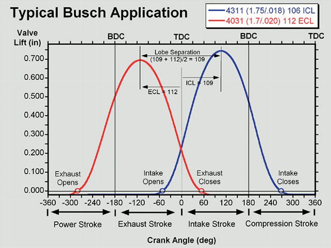 A cam chart like this can tell you just about everything you need to know about a cam. This is a typical design used in the Busch Series. The red line shows where the cam has the exhaust valve positioned in terms of lift for every degree of the crank's movement. The blue line is for the intake. Where the two lines intersect is valve overlap. The circles at the bottom mark lift at 0.050 inch. Courtesy of Comp Cams
Base Circle is the term for the backside of the lobe. When the lifter is on the base circle of the lobe, the valve should be closed. It is also commonly called the heel of the lobe. The size of the base circle is important in relationship to the cam's lift. A smaller base circle allows more lobe lift, but it can also allow the camshaft to flex and throw off the timing events.
Ramps are the parts of the lobe where the lifter is either moved up or allowed to drop. Every lobe has two ramps-an opening ramp and a closing ramp. In performance camshafts, the curve of the ramps changes several times, which is a tool the cam designer uses to fine-tune the speed and acceleration of the lifter.
An asymmetrical lobe refers to opening and closing ramps that are not identical. In order to maximize both valve speed and control, the lifter must be raised in a different manner from which it is lowered. For example, in performance applications the valve is generally opened as quickly as possible, but the speed of the valve slows significantly as it nears maximum lift to keep it from lofting. But on the closing side, the valve must be seated relatively gently to keep it from bouncing. An asymmetrical lobe design allows this.
The nose of the lobe marks the area where the valve is fully opened. The highest point of lift is the lobe's centerline. The intake centerline is measured as crankshaft degrees after top dead center (TDC). The exhaust centerline is expressed as the number of degrees of the crankshaft's position before TDC. Incidentally, a cam's position is always measured relative to the crankshaft's position because that tells you where the piston is and which stroke it is on (intake, compression, power, or exhaust).
Lobe lift is the amount the cam lobe raises the lifter. It isn't the same as valve lift because the rocker arm is a lever that multiplies the amount of lobe lift to get the final valve lift. The lobe lift is equal to the diameter of the lobe at the centerline minus the diameter of the base circle.
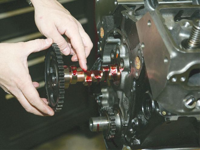 Many cams are ground with 4 degrees of advance built-in, but that isn't always the case with race cams. You can experiment by advancing and retarding the camshaft a couple of degrees with special adjustable timing sets to see if the changes give you any benefit on the racetrack.
Obviously, the primary job of the camshaft is to control the timing of the intake and exhaust valve events. This is done with separate intake and exhaust lobes. The relationship of these lobes to each other is called lobe separation. Lobe separation is measured in degrees between the peak of the exhaust lobe (maximum valve lift) and the peak of the intake lobe. Essentially, it is half the angle in crankshaft degrees of rotation between peak exhaust valve lift and peak intake valve lift. If the duration remains the same, increasing the lobe separation angle decreases overlap, while decreasing it does the opposite.
"Typically, if all other factors are kept constant, widening the lobe separation produces a wider, flatter torque curve that holds better at higher rpm but can sometimes cause a lazy throttle response," explains Billy Godbold, a camshaft designer at Comp Cams. "Tightening the separation generally produces the opposite effect-more mid-range torque and a faster revving engine, but with a tighter power range."
There are other reasons to change lobe separation to influence engine performance. For example, if you are running a long rod package and keep the stroke the same, you will dwell the piston near TDC longer. To maintain similar overlap characteristics, you may need to open up the lobe separation and shorten the duration.
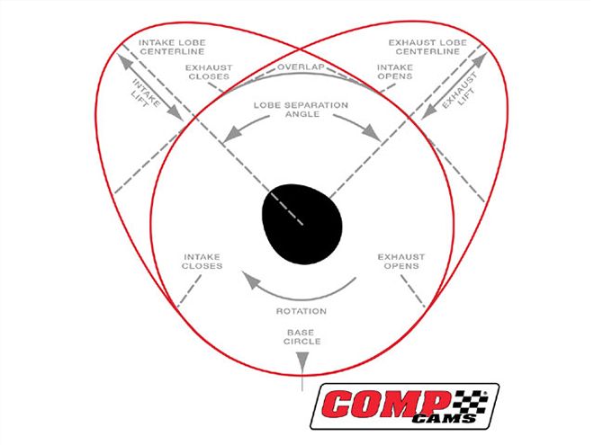 This diagram shows many of the critical areas on the cam lobe as well as the relationship between the intake and exhaust lobes. Courtesy of Comp Cams
Overlap is the point in crank rotation when both the intake and exhaust valves are open simultaneously. This happens at the end of the exhaust stroke when the exhaust valve is closing and the intake is opening. During the period of overlap, the intake and exhaust ports can communicate with each other. Ideally, you want the scavenge effect from the exhaust port to pull the air/fuel mixture from the intake port into the combustion chamber to achieve more efficient cylinder filling. A poorly designed cam and port combination, however, can cause reversion, where exhaust gases push their way past the intake valve and into the intake tract.
Several factors influence how much overlap is ideal for your engine. Small combustion chambers typically require minimal overlap, as do engines designed to maximize low-rpm torque. Most current stock car racing engines depend on high rpm to take advantage of better gear ratios, so more overlap is normally helpful. When the revolutions per minute increase, the intake valve is open for a shorter period of time. The same amount of air and fuel must be pulled into the combustion chamber in less time, and the engine can use all the help it can get to fill the chamber. Increasing the overlap can help here.
Long rod/stroke packages, which are becoming increasingly popular in circle track racing, also have an effect here just as with the lobe separation. Because the piston dwells near TDC longer, it makes the combustion chamber appear smaller to the incoming air/fuel charge. Because of this, less overlap is needed to properly fill the chamber. Along with reduced vacuum and potential reversion problems, running too much overlap in your race engine sends unburned fuel out of the exhaust pipes, reducing fuel efficiency. For most short track racers, this isn't a problem. But if you run into a fuel-mileage situation to cut out pit stops, it can be helpful.
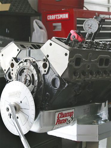 When degreeing your cam, always use the duration provided for when the lifters are at 0.050 inch lift. At this much lift, the lifters have a greater velocity than the normal advertised duration (anywhere between 0.004 and 0.020 inch) which allows you to be much more accurate.
Duration is the amount of time, measured in degrees of crankshaft rotation, that the valve-either intake or exhaust-is open. Most camshaft manufacturers list both an advertised duration and duration at 0.050 inch. We'll discuss this in more detail later.
As engine rpm increases, the engine eventually reaches a point at which it has trouble effectively filling the cylinders with the air/fuel charge in the short amount of time the intake valve is open. The same thing holds true with the spent exhaust gases. The simple answer here is to increase the amount of time the valve is open, which is referred to as increasing its duration. For example, to maximize flow during the exhaust stroke, many extreme performance cam designs begin opening the exhaust valve near the midpoint of the power stroke. This may seem harmful to power production, but the idea is to have the exhaust valve fully open when the exhaust stroke begins. During the power stroke, the burning fuel has used about 80 percent of its available force on the piston by the time the crank has turned 90 degrees. The bottom half of the power stroke actually provides very little in terms of engine power, and it can be better used to help exhaust the combustion chamber so that there is more efficient cylinder filling on the intake stroke.
Here's a statement that you already know: The valve is most efficient at allowing air (either intake or exhaust) to flow past it when it is fully open. Not to insult your intelligence, but we needed to get that out of the way. What that statement tells us is that in terms of achieving maximum engine performance, the amount of time the camshaft is either raising or lowering the valve is effectively wasted. In a perfect world, the valve would be completely seated to seal the chamber, then it would fully open instantly at the appropriate time to allow maximum flow.
To get as close to this as possible, maximum race cams use extreme lobe profiles that open and close the valve ridiculously quickly. This requires stronger valvesprings and lightweight valvetrain components to maintain valve control, and engine builders and cam designers alike are still researching ways to open the valves even faster.
A more aggressive cam with high lift velocities allows you to shorten the duration in certain situations, which can help power. "Aggressive ramps allow the valve to reach maximum velocity sooner, allowing more area for a given duration," says Godbold. "Engines with significant airflow or compression restrictions [often seen in Street Stock classes or other classes with small carburetors] seem to love aggressive profiles. This is likely due to the increased signal to get more of the charge through the restriction. The decreased seat timing also results in earlier intake closing and more cylinder pressure."
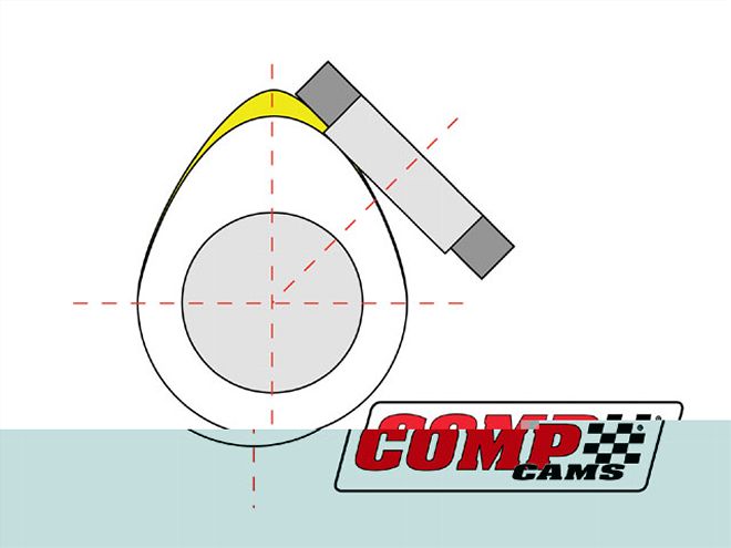 If you are required to race flat-tappet lifters, always try to use the largest lifters available. This requires honing the lifter bores, but it is often worth it. As you can see from this diagram, the smaller lifter (light gray) is limited to the rate of lift in the lobe before the edge starts digging into the camshaft. The larger lifter can be used with a much more aggressive lobe. Courtesy of Comp Cams
Currently, one of the greatest limiting factors when it comes to aggressive camshaft profiles is the requirement many tracks and sanctioning bodies have mandating flat-tappet lifters. A flat tappet limits how quickly you can raise the lifter because the lobe angle can only be raised a specific amount before the edge of the lifter begins digging into the side of the lobe. Increasing the diameter of the lifter allows the lifter to slide over the face of the lobe again, so if your rules allow, try running a larger lifter combination. Godbold provided us with a few interesting numbers concerning maximum velocities for lifters. For example, with a stock Chevy 0.842 diameter lifter, the maximum velocity is 0.00700 inch per degree. If you use a Ford 0.875 lifter, that increases the maximum lift to 0.00735 inch per degree of rotation. That may not sound like much to you and me, but it's enough to make a cam designer drool. Of course, those numbers pale in comparison to a roller lifter, which doesn't have the same limits and is definitely the way to go in a racing application if the rules allow it. The maximum velocity for a performance roller lifter is typically around 0.009 per degree. Now we are talking about a really big difference.
One thing that confuses many new racers is that cam companies typically list both an advertised duration and a duration measured when the lifter is 0.050 inch off of the seat. The problem is that different manufacturers use different points to determine duration. There are different reasons for this, but few of them concern anyone other than the cam designers and their respective marketing departments. That's why lift at 0.050 has become an industry standard.
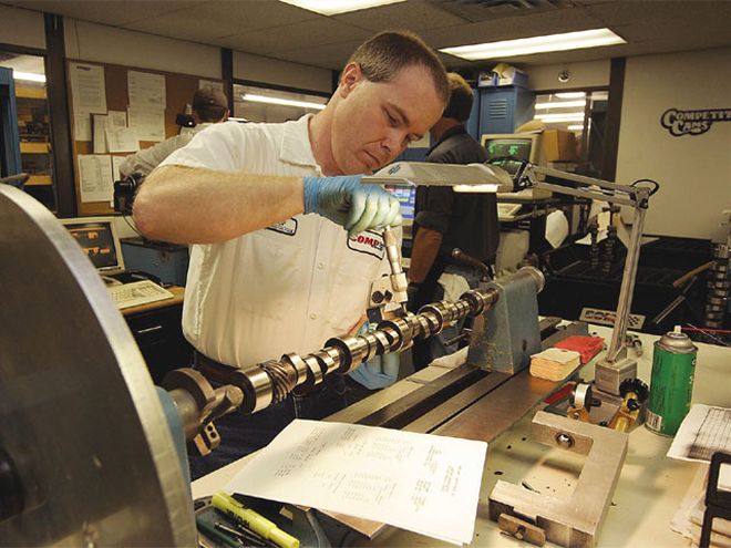 The good news is that when it comes to high-performance cams, companies such as Comp Cams have hundreds of lobe grinds on file that are mixed and matched to fit your engine package. Sometimes they aren't even in the catalog. Don't be afraid to get in touch with someone in the tech department. Give that person the engine combination you plan to run and the rules for your class, and use that person's experience to help you determine what works best.
Usually, a valve doesn't begin flowing a significant amount of air until it has been raised several thousandths off of the seat. Also, differences in lash make it difficult to determine the exact moment a valve leaves the seat. Finally, duration at 0.050 inch of lobe lift is easier to measure and makes life easier for anyone setting the cam timing with a degree wheel. " . . . it's easier to measure the 0.050 duration than the advertised duration because the tappet velocity is much higher after it has had some time to accelerate," Godbold explains. "When using a cam degree wheel and a dial indicator, there is far less uncertainty about where the degree wheel is oriented when the dial indicator reads exactly 0.050 inch of lift than with lifts in the 0.004 to 0.020 range."
By using special timing sets, you can change the angle of the cam relative to the crankshaft. Spinning the cam forward so that the valve opening events happen sooner is called advancing the cam. Retarding the cam is just the opposite. Most camshaft manufacturers grind in around 4 degrees of advance into their cams so that it is automatic when you install your cam with the zero marks on the timing set. This is very common with street cams but varies with different race cams. Make sure you know what you have.
"Typically, engines respond better with a few degrees advance," Godbold explains. "This is likely due to the importance of the intake closing point on performance. Earlier intake closing leads to increased cylinder pressure and better responsiveness." As a general rule of thumb, advancing the cam will help low-end torque, but if your engine is dying by the flag stand, retarding the cam a few degrees should help extend high-rpm power a bit.
The information we've provided is a lot to digest, but don't worry. Most cam manufacturers have helpful tech departments to work you through the rough spots. To make things just a little easier, here's a cheat sheet for cam changes and the typical result. Remember, all engine packages are different, and your results may vary. These are only general guidelines.
Cam Change: Typical effect More Lobe Separation: Wider powerband, more peak power,