Have you ever been to a dirt track and watched a World of Outlaws winged sprinter race? No? Then that is most certainly your loss. What you are missing is truly spectacular racing and the chance to see a vehicle with a very high degree of optimization of moment of inertia. Listen to one of these 400-inch, 800hp injected alcohol monsters rev up, and the greased-lightening throttle response leaves the impression that it defies the laws of physics. It sounds as though it's digital (a step function) rather than analog (a progressively increasing function). In other words, it sounds as if it goes instantly from 1,200 to 7,500 rpm. This eardrum-fraying whiplash lets you know right away this is not an engine for the faint-hearted.
Sprinter-like throttle response is a target I strive for (to a varying degree) with every engine I build. Although having an effective engine spec in terms of induction, compression, cam, and ignition is half the battle, it's important to realize that it really is just that--half the battle. The very overlooked other half is moment of inertia.

Let's cut any pretense at suspense; exactly what is moment of inertia? As per Sir Isaac Newton's Third Law of Motion, every object in a state of uniform motion tends to remain in that state of motion unless an external force is applied to it. The moment of inertia of an object is, in the context we are dealing with here, its resistance to rotational acceleration. For example, a big, heavy flywheel will take more engine torque to accelerate it up to speed than a smaller, lighter one. But there's more to it than just the amount of mass to be accelerated. The radius at which the mass resides also has a major influence on how rapidly an object can be rotationally accelerated. The basics (and fortunately, that is all you need to know) of what we're leading up to here are not at all difficult to understand. Fig. 1 should put you clearly in the picture. What we see here are two flywheels of the same weight. The significant difference is that one has the weight concentrated toward the outside of the flywheel, the other toward the center. The one with the mass in the center will accelerate far quicker for a given applied torque than the one with the mass at the outside.
The fact is, both mass and the radius at which it operates are our enemy. Understanding the concept and consequences of inertia reduction is the key to unlocking the existing power in your engine. What you probably don't appreciate is the truly staggering effect the unwanted mass, acting at an unnecessarily large radius, has on the rear-wheel horsepower of a car. This is what we intend to set straight, by covering eight areas successful race-car builders optimize in the transmission of power between the engine and the drive wheels. To do this, let's start at the engine and work our way back through the drivetrain to the driving wheels.
FIG. 1 Although both of these flywheels weigh the same, the lower one will spin up easier because the mass is located nearer the center, giving it a lower moment of inertia.">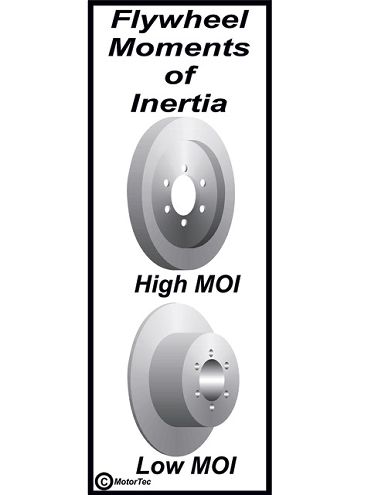 <strong>FIG. 1</strong> Although both of these flywheels weigh the same, the lower one will spin up easier because the mass is located nearer the center, giving it a lower moment of inertia.
Three Key Items: Crank, Rods, and Pistons
When I was a kid, I often wondered where the energy of the piston and connecting rod's mid-stroke speed went at each end of the stroke. Although not intuitive, the answer is that in slowing the piston and rod assembly down, the energy is absorbed into the crank (which tends to increase crank speed). When speeding up, the piston and rod assembly absorbs energy from the crank (which slows crank speed). In other words, this assembly acts as if it is a small flywheel with fluctuating mass. This means not only do we need to reduce piston and rod weight to relieve the crank of unnecessary reciprocating loads, but also to reduce its flywheel effect.
Cutting piston and rod weight has a positive knock-on effect on the crank design. When the piston and rod assembly becomes lighter, the amount of counterbalance mass needed on the crank becomes less and usually by a bigger amount. Not only does this reduce flywheel effect, but it also cuts windage. As to how much crank windage reduction is worth, it's not something for which I have a simple answer because I have not really built a 9,500-rpm engine with an ugly, high-windage crank to find out what a low-windage one will do in its place. What I can tell you is that the result of my flat-versus-aero counterweight crank test (a Scat crank in an engine operating in the 7,200-rpm range) revealed almost a 10hp increase. Cutting piston mass so that a lighter and more aerodynamic crank can be used means an increase in static horsepower and a decrease in power absorbed by having to accelerate that mass. We have a good idea of what can be had by improved windage, so now is the time to look at the proportions of what may be gained by reducing the flywheel effect of the rotating assembly.
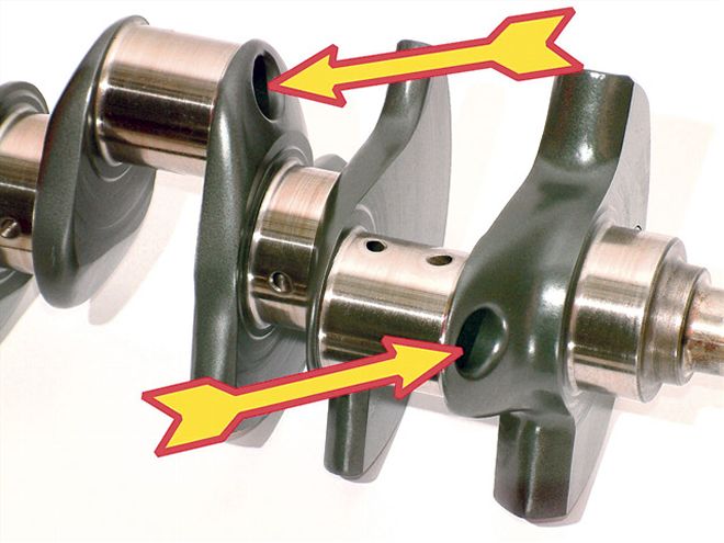 This detailed $220 Scat aero crank has over .25 inch more stroke, but weighs 1.5 pounds less than a stock cast crank, partly because of the hollow big-end journals. Even with the longer stroke, moment of inertia remains about stock.
Item Number 4: Measuring the "Flywheel Effect"
When a large dyno manufacturer got into the business of dynamometers back in the early '80s, I was already a dyno-testing veteran of some 20 years. At this point, I already had experience with all the major brands of dynamometers. But this company did something with its dynos none of those others did (at least not at a price that anyone outside of GM or the like could afford), namely, to allow the engine to be tested at various user-defined rpm acceleration rates. This allowed the simulation of engine operation in any gear from First to High. I was so enamored with the capabilities of the then-new dyno that I bought one of the first ones. What this dyno allowed me to do for the first time was to test the differences produced by rotational assemblies of high and low moments of inertia. I already knew that "low" was better by a bunch, but up until this stage could not put any figures on it. Now, using a relatively mundane 350 small-block Chevy, things were about to change.
A call to Red Roberts at McCloud Industries got the ball rolling. Red sent over a couple of flywheels, one about 30 pounds, and the other about 10 pounds. The effects that these flywheels would have on output were tested on a nominally 375-horse mule motor. Tests were done in three modes: steady state, plus acceleration rates of 600 rpm-per-second and 300 rpm-per-second. These acceleration rates approximated engine acceleration in Second and Fourth gear of a typical five-speed gearbox.
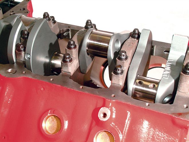 This forged, internally balanced, Lunati 4-inch stroke small-block Chevy crank with its hollow big-end journals is affordable for the serious engine builder and weighs just less than a stock 350 crank.
Because the flywheels were of a different design, the moments of inertia did not directly transpose at the same ratio as the weights did. All I knew for sure here was that the 10-pound flywheel had a considerably lower moment of inertia than the 30-pound one. Fig. 2 shows the test results.
From the curves in Fig. 2, it is easy to see that cutting the flywheel effect allows much more of the available steady-state horsepower to be accessed during acceleration. The chart in Fig. 3 shows the gains at 300 rpm/sec (simulating Fourth gear) and 600 rpm/sec (simulating Second gear) when the 30-pound flywheel was replaced with a 10-pound item.
 Don't put any more rod into your engine than necessary. These detailed budget lightweight 4340 rods from Scat serve well in engines up to about 525 hp.
These tests definitely point toward a lighter moment of inertia being better for performance, but are there downsides? The principle reason the factory puts heavier flywheels on is for idle quality. The flywheel's mass smoothes out the engine's compression and firing impulses. Here, the crank slowing caused by the compression stroke is a significant deal. Fortunately, when we install a longer-period cam, the amount of flywheel effect required to smooth out the compression stroke is reduced. An example here gives an idea of the significance of the required flywheel/clutch rotating weight in relation to the cam used. The engine in question is a 13:1 compression (it runs 100-octane fuel) F.A.S.T.-injected, street-driven 440-inch small-block Chevy. It pumps out right around 700 hp and 600 lb-ft. This prodigious output is transmitted to the rearend via a super-light Fidanza flywheel and a small-diameter twin-plate clutch (good for about 900 hp) from Clutch Masters. Because of the 297/304 degrees of off-the-seat duration, the engine idles at a steady 700 rpm with a clutch/flywheel inertia about 75 percent less than stock. Remember that Sprinter throttle response mentioned earlier? This engine, due to the small-diameter clutch and the lightweight flywheel, has got it by the boatload.
So far, the situation looks good for a low-inertia clutch/flywheel assembly, but the dyno tests only point us in a direction toward more driving wheel output. What they don't take into account is the fact that these flywheel tests were run only with the inertia of the engine's rotating mass and the dyno's absorber mass. In the real world, cars have clutch, transmission, and wheel inertia to deal with, as well as launches from the start line, which can rely greatly on stored kinetic energy. It is possible for this--especially for the drag racer--to skew the picture somewhat. The question is, which way is the skew?
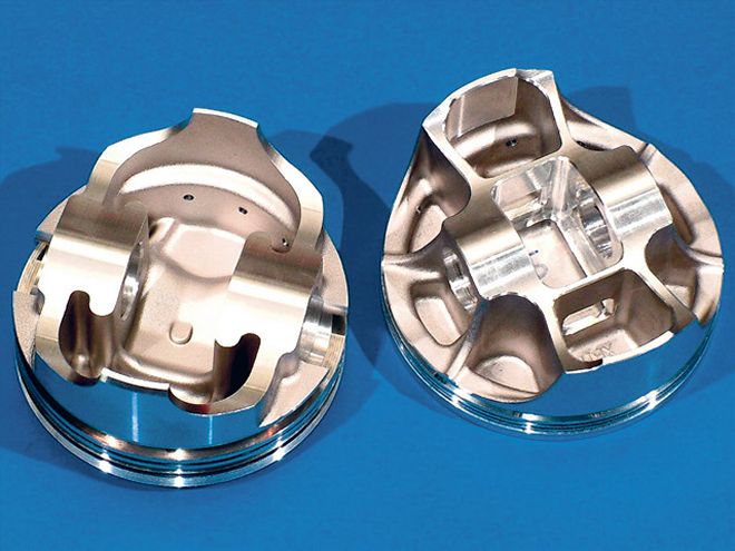
 The CP Cup Car piston (right) is a complex high-tech forging with a lot of internal machining. It's light, and you will pay an appropriate price. Not quite as light, but a lot less money, is the new KB forged piston. It's worth checking out if you are on a tight budget.
The Low/High Moment of Inertia Flywheel Controversy
A lot of successful "old-school" racers claim best e.t.'s are made by harnessing the considerable kinetic energy potential of a heavy clutch and flywheel assembly for a harder launch. The theory is simple: First, pump horsepower into the flywheel prior to leaving the line by revving 500 to 700 rpm past peak power. At this point, pull rpm back by clutch control to about peak torque as the car is launched then retrieves much of this stored energy. There is no doubt this technique delivers more "available power" for the most critical part of any fast quarter-mile pass, namely the start. On the downside, the flywheel will, during the time the rpm climbs back up to the shift point, absorb torque from the engine. As the shift is made, the rpm is once again pulled down and in the process energy in the clutch/flywheel assembly is transferred to the car. Up to this point, the theory sounds good, but to transmit the entire inertial energy content from the higher rpm to the lower rpm requires that neither the tires nor the clutch slip. If any slip occurs within the system, it means that some kinetic energy has been converted to heat rather than forward motion of the car.Proponents for light clutch/flywheel assemblies point to the fact that there is more available power when the engine has less rotating mass to accelerate. The lower the gears involved, the more rapidly the rotating parts are accelerating. This, as the graph in Fig. 4 shows, results in a greater amount of power being absorbed during acceleration. This means after the clutch is fully engaged, the clutch/flywheel absorbs the greatest amount of power (and a heavier one moreso) in First gear right when all the power possible is needed to launch the car. The real-world difference in output between First and Fourth gear for a drag-racing factory-stock 5.0 Mustang test car was a mind-boggling 140 lb-ft and 85 hp!Such a huge loss begs the question as to why this occurs. In the case of the test vehicle in question, we find that although the car itself may have only accelerated to about 35 mph in First gear, the outside diameter of the flywheel actually hit over 220 mph. On the road, its mass not only has to be accelerated forward, but also rotationally. Cutting such losses means, for road-race situations, there is potential for more rear-wheel power without actually having to modify the engine for more output, but for the drag racer, the situation is not quite so clear-cut.
Success on the strip requires a fast launch for low 60-foot times. For a road racer, the start (though hardly immaterial) is far less important, as any advantage a heavy clutch/flywheel has is cancelled out upon arrival at the first corner. From the exit of the first corner on, the lowest inertia (lightest rotating parts) is absolutely the way to go. But for drag racing, the case for lighter flywheels with a low moment of inertia is still a topic of some debate.
FIG. 2The green line is a steady-state test, and since the engine is not accelerating, the flywheel weight made no difference. This was not the case at the 600 rpm/sec acceleration rate (simulating Second gear) where the 10-pound flywheel made almost 22 hp more than the 30-pound one.">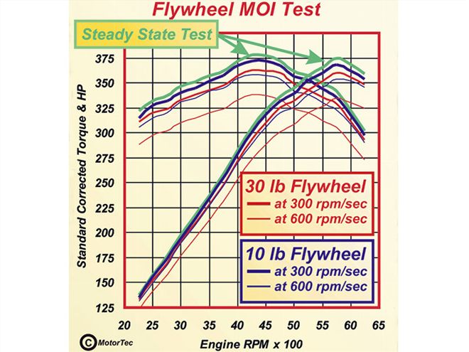 <strong>FIG. 2</strong>The green line is a steady-state test, and since the engine is not accelerating, the flywheel weight made no difference. This was not the case at the 600 rpm/sec acceleration rate (simulating Second gear) where the 10-pound flywheel made almost 22 hp more than the 30-pound one.
The Big Plan
Knowing my keen interest in inertia testing, Chris Jewell of Competition Clutch gamely volunteered to organize some track and dyno time. Accomplices here were Robin Lawrence with what is now his ex-12.5-second factory-stock 5.0, and Craig Baldwin with a Vortech-blown NMRA Real Street 10.5-second car.The plan was to test a stock-weight flywheel (23.75 pounds and a moment of inertia of 1.614 in-lb-sec2 against a lightweight Fidanza flywheel at 10.8 pounds and a moment of inertia of 0.771 in-lb-sec2. This represented a weight and moment of inertia reduction right around 55 percent. This was deemed a sufficient difference to easily show differences in our before and after tests.
Dyno Test and Results
The first move was to put Robin Lawrence's factory-stock 5.0 Mustang on a Dynojet chassis dyno. The test procedure involved rolling smoothly from low rpm to full throttle in First gear. At the shift-light prompt, Second gear was grabbed as per a live dragstrip run. At the 2-3 shift point, the test was terminated. Instead of rpm, the power figures were measured against speed and time. This would allow us to see both the "in-gear" power absorption of the accelerated rotating parts and whatever portion of returned stored energy that might appear as additional rear-wheel horsepower during the shift.
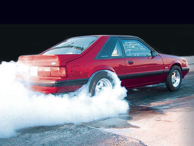 The only place to be sure our theory and dyno testing produce the expected results is to do real-world testing. With a pair of fast 5.0s, that's just what was done.
Before and after dyno test comparisons on both test vehicles (Fig. 5 and 6) clearly show that reducing the rotating mass helps horsepower during the "in-gear" accelerating phase. The dyno tests also show flywheel energy being reintroduced into the drivetrain/wheels during the shift (the area between the red and blue curves as indicated by the green arrows in Fig. 5 and 6). Here, the heavier flywheel produced higher figures during that transitional shift period. After the shift, when the clutch was fully engaged, the lighter rotating assemblies once again showed their superiority.
The tests with the Vortech-supercharged 5.0 showed similar trends to the factory-stock 5.0, but in different proportions. Check out the curves in Fig. 6. Because this Vortech-equipped engine was of far greater output (especially in terms of lb-ft), the test had to be done in Second and Third gears. Per the factory-stock 5.0, the lighter flywheel delivered more power.
FIG. 4Here is the output of a factory-stock 5.0 drag racer as measured in First and Fourth gears. The staggering 140 lb-ft and 85hp difference between the two is due to the power absorbed by the moment of inertia of the entire rotating mass from crank to wheels. Reducing the inertia can cut these losses considerably.">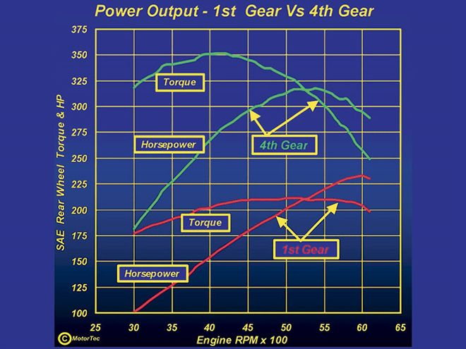 <strong>FIG. 4</strong>Here is the output of a factory-stock 5.0 drag racer as measured in First and Fourth gears. The staggering 140 lb-ft and 85hp difference between the two is due to the power absorbed by the moment of inertia of the entire rotating mass from crank to wheels. Reducing the inertia can cut these losses considerably.
The shift light prompted the shift to be made, but because the lighter parts accelerated faster; an identical response time meant the rpm went a little higher between shifts. This makes the comparison during the shift phase (green arrow area) a little difficult to make. The time difference meant the shift with the lighter parts was some 150 rpm higher than with the heavy parts. Although this was not intentional, this test does start to show another factor in the equation, namely the effect increased rpm has on the energy available at the shift point. Check the shape of the curves and the distance apart in the region indicated by arrows in both Fig. 5 and 6. There is a much bigger area on the factory-stock 5.0 than on the Vortech-blown 5.0. This bigger area represents the difference in energy being paid back to the driving wheels during the shift. The amount of energy involved is proportional to the mass but also proportional to the square of the rpm, i.e., rpm X rpm. With the Vortech-blown car, the additional 150 rpm and the resulting 5 percent more energy before the shift with the lighter rotating mass added what appeared to be almost enough additional energy to compensate for the lower moment of inertia of the lighter flywheel involved.
We have established three facts from the dyno tests:
*With full clutch engagement, a low moment of inertia clutch/flywheel assembly produces more driving wheel horsepower.
*Assuming the same shift rpm during the shift phase, a high moment of inertia clutch/flywheel can return more stored energy than the low moment of inertia setup can.
*If more rpm is used with the low moment of inertia clutch/flywheel, the difference in stored energy can be totally compensated for.
At this point it is apparent that though some questions have been answered, we are still left with the most important one: Does the stored energy of the heavier setup, which is available for the launch and each subsequent upward shift, compensate for the reduced output during full clutch engagement periods? The most critical part of a fast quarter-mile time is the launch. Here, the extra energy of a heavy flywheel is available with no prior penalty. This makes the answer to "heavy or light" anything but obvious in the case of the lower-output factory-stock machine. The Vortech-blown 5.0 though is much nearer a clear-cut case of light is better. Why? Because we can see from the dyno tests that a small increase in launch rpm will cancel out any advantage the greater rotating mass may have had on the start line. At least in the case of the factory stock car, it now looks like time to go to the track and settle this debate.
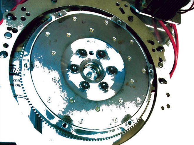
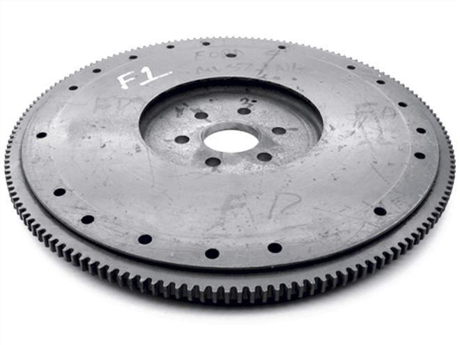 At 23.75 pounds, the stock 5.0 flywheel was a monster...
Track Time
Cordova Raceway near Moline, Illinois, was the venue for our track testing, and thanks must go to track owner/manager Scott Gardener and his management crew for catering so well to our needs. The main focus of our trackside attention was on the street tire-equipped factory-stock machine because: a) The higher percentage of released energy at the shift, and b) It was equipped with an Auto Meter data-acquisition system.
Experience shows that with the heavier of the clutch and flywheel assemblies being tested, best 60-foot times were achieved by leaving with 3,000 rpm on the tach. As the Auto Meter data-acquisition system showed, any more than 3,000 rpm, the tires would momentarily break loose; any less, and the motor would go into an almost imperceptible bog. After making five consistent runs, the numbers were averaged out to show the factory stocker was running 12.390 seconds at 109.757 mph.
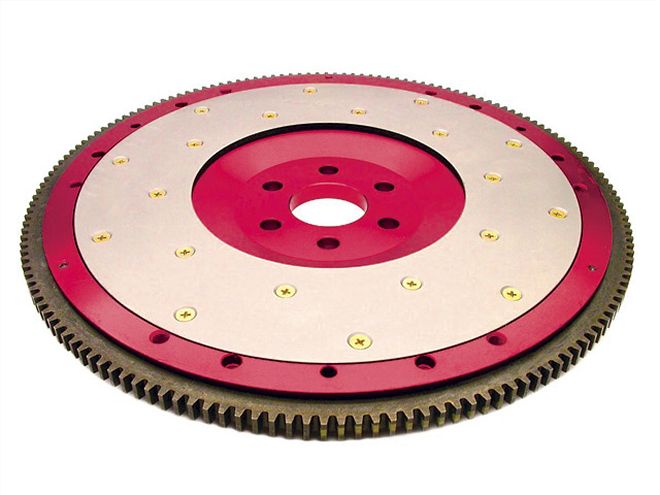 ...compared to the svelte 10.8 pounds of this Fidanza flywheel.
Less Mass: The Results
After the lighter clutch/flywheel assembly was installed into the factory stocker, it was evident that launch tactics had to be revised. The e.t. slip told us the average 60-foot time had increased. The Auto Meter data-acquisition system showed engine rpm was dropping far more during the clutch engagement period. The fix was obviously more rpm at the launch. Working this up to an optimum figure produced a 3,500-rpm launch instead of the original 3,000. The results of these tests are shown in Fig. 7. As you can see, the lighter clutch/flywheel with a higher launch rpm won out everywhere except, for some unknown reason, the eighth-mile speed. Over a tenth was shaved off the e.t. and the trap speed was up by a little over six tenths of a mph, proving (in this case) lighter is better!
When baselined with the heavy flywheel, Craig Baldwin's Vortech-blown machine's best start-line rpm proved to be 4,600. The average of three close runs produced a 10.863 e.t. With the lighter flywheel installed and a new optimum launch rpm of 5,000, the three-run e.t. average dropped to 10.725. That was more than significant by itself, but Fig. 8 reveals more. These more-comprehensive numbers showed the trap speed did not follow in step with the e.t. improvements, but actually dropped almost 1.5 mph. Although the time for testing was over, the cause for the car to slow past the 1,000-foot mark was investigated. Heat buildup from so many runs was suspected. After cooling for about an hour, a blistering 132-mph pass was made, indicating that our tests, though very much positive, had not pulled the best possible numbers from the lightweight clutch/flywheel setup.
FIG. 5Here are the dyno tests of the factory-stock 5.0. This shows the light flywheel as superior everywhere other than during the shift phase (arrowed green). For about a tenth of a second during the shift phase, the heavy flywheel delivered some 40 hp more than the light one.">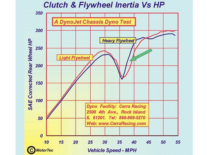 <strong>FIG. 5</strong>Here are the dyno tests of the factory-stock 5.0. This shows the light flywheel as superior everywhere other than during the shift phase (arrowed green). For about a tenth of a second during the shift phase, the heavy flywheel delivered some 40 hp more than the light one.
Before we wrap up this section on flywheels, it's worth looking at just how much weight we would have to remove from the car itself to equal the effect of the 20-pound-lighter flywheel. If the heavy flywheel was retained, then the car--to equal the First-gear acceleration given by the light flywheel--would have to be reduced by 272 pounds. The equivalency figure for Second gear would be 187 pounds; Third, 127 pounds; and Fourth, 98 pounds. At this point, we think we can safely say lighter is better!
Item 5: The Other Flywheel
No matter what rules seem to apply to a given situation, there always seems to be an exception. The moment of inertia of an object up at the front end of the engine is just such an exception. It's called a crankshaft tortional vibration damper, or crank damper for short. Back in the '80s, even top drag racers were substituting heavy crank dampers for lightweight aluminum "hubs" in the belief they would go faster. The reality is these hubs, although having a vastly lower moment of inertia, actually cut power, even under high-acceleration conditions. The reason they did so is that they did not suppress crank tortional flexure. Such vibrations were transmitted directly to the cam via the timing chain and, as a result, the valve event timing was adversely affected and valve bounce was aggravated. All this led to a reduction in power, and I'm not talking .5 to 1 hp here, but sometimes 12 to 14 hp on a 400-odd-hp engine. The bottom line here is, use a functional damper first and worry about its moment of inertia last. That way your motor will make more horsepower, longer.
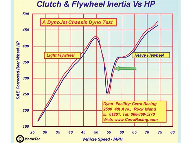 <strong>FIG. 6</strong>Shown here are the results from the Vortech-blown car. Note that due to a slightly higher shift point, the advantage of the heavy flywheel over the light one is diminished as shown by the area indicated by the green arrow.]
Items 6 and 7: Drive Shafts and Axles
This section will be short and sweet. The driveshaft is such a small diameter that if a steel one was replaced with one having zero mass, the increase in driving-wheel horsepower in First gear would be barely perceptible. As a performance-enhancing device, it has near-zero value. Where it does score is the fact that rear unsprung weight is reduced by about half the weight reduction of the driveshaft itself. The same applies to lightweight gun-drilled axles, except all the weight saving is realized as unsprung mass.
Item 8: Lightweight Wheels and the Big Payoff
Let's start with wheel moment of inertia first, because the tire moment of inertia situation is one where we have less room to maneuver, thereby making our choice much simpler.
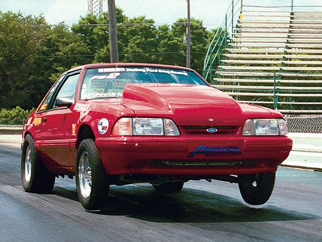 Driver consistency is the key to good testing. Run after run, Craig Baldwin would catch 6 inches of air at the launch.
The mass of a live rear axle is one of the most offensive aspects of a production-based, Detroit-built, high-performance street or race car. Using a 5.0 Mustang as an example, the axle weighs in at about 220 pounds with brakes, but less wheels and tires. A set of wider wheels and tires bought without due consideration to how much they may weigh can add a further 100 pounds to this already-burdensome figure. This totals some 320 pounds of unsprung weight at the back. If we add to this about 80 pounds a side for the front suspension, we can see that of the car's 3,200 pounds stock weight, some 480 pounds, or 15 percent, is unsprung. One of the first steps many will take toward improving the car's track-day performance or race worthiness is to lighten it. Sticking with our Mustang, we find that by the time the heater and A/C are removed, along with the 5-mph crash bumpers, door bars, sound deadening, and back seat, about 400 pounds have come out of the car. If no attention has been paid to the unsprung weight, the ratio of one to the other has deteriorated to well over 17 percent. This means we need to give some serious attention to unsprung weight. The greater the unsprung weight, the greater the amount of energy transmitted to the chassis when riding an uneven surface. This reduces grip during acceleration, braking, and cornering modes. It also cuts the effectiveness of any anti-squat that may be built into the rear suspension system. This make the 60-ft times longer at the dragstrip.
There is more to lightweight wheels than just the simple, but nonetheless important, reduction of moment of inertia due to rotation. Most PHR readers drive cars with a lot of unsprung weight in the form of a heavy rear axle. This can have a lateral moment of inertia that can, under certain commonly occurring conditions, significantly affect road holding and handling. Here is a quick rundown: The worst kind of bump a live axle has to deal with is the type where both wheels hit at once, as per a speed bump. This is bad because the entire mass of the axle/wheel assembly is involved. A reduction of unsprung weight here is worthwhile, but to far less of an extent than if just one wheel (as is more commonly the case) of the axle pair hits the bump. When this is the case (as per Fig. 9), the axle looks like a long arm with its center of rotation at the contact patch of the opposite wheel. Although most of the axle mass is in and around the diff housing, this is only half the distance from the center the axle is rotating about. The wheel and tire assembly, though, is right out as far as it can be from the rotation center. What this means in such a bump scenario, is that taking a couple of pounds out of the wheel does far more than just the percentage the unsprung weight is dropped by. Just how much effect wheel-mass reduction has in this instance is dependent on the severity of the bump. But on average, you can safely assume that with a typical live axle, a 10-pound-weight savings at the wheels will be about equal to 30 pounds off the axle.
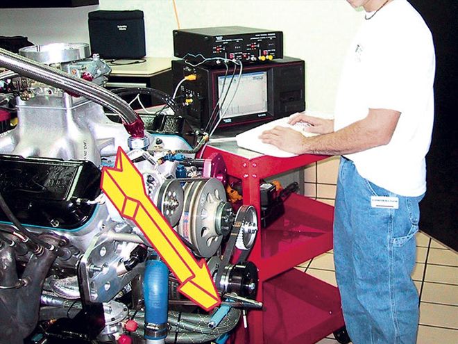 JC Beattie of ATI is seen here using the company's portable equipment (crank pick-up arrowed) to run a damper test at Dale Earnhardt Inc. By manipulating rubber characteristics and inertia mass of the ATI damper, JC reduced crank deflection to less than 0.2 degrees double amplitude. This was worth more power than an otherwise lower inertia damper.
Now let's get down to wheel weights for a typical Detroit-based g-Machine. A typical set of 17-inch- diameter, 9-inch-wide cast-aluminum wheels with a set of tires can weigh in at as much as 54 pounds, with 50 being relatively common. By selecting a set of cast/forged one-piece wheels and suitably grippy tires on the basis of weight, it is possible to get that figure down to 42 pounds. If a modular three-piece competition-style wheel is used, the weight can drop even further to some 34 pounds. Assuming 50 pounds apiece to start with, the weight reduction could amount to 16 pounds per corner, for a total of 64 pounds off the vehicle, and more importantly, 64 pounds off the unsprung weight. Looking at the percentages, and including the reduction in overall weight, we now find that the ratio of unsprung to sprung weight has dropped to 14.5 percent. Finally, a number less than was seen with the stock machine.
The same treatment can be done on the front suspension. Such things as tubular A-arms and lightweight brakes plus an intelligent choice of wheels can make a significant reduction in the unsprung mass.
The savings delivered by brakes and other suspension components are easy to see, but wheels deliver far more than a reduction in unsprung weight. Not only do they have mass that is moved up and down with the suspension and forward with the car as a whole, but also rotational inertia. Saving weight on a wheel not only means a total weight savings four times greater, but also a reduction in moment of inertia. This in itself adds up to a whole lot more in terms of performance gains than just the weight saving itself.
FIG. 9If only one wheel hits a bump, as is most often the case, weight saved at the wheel is equal to about three times the amount of the axle.">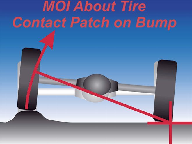 <strong>FIG. 9</strong>If only one wheel hits a bump, as is most often the case, weight saved at the wheel is equal to about three times the amount of the axle.
Demonstrating Rotational Moment of Inertia
To demonstrate what lightweight wheels are worth on the dragstrip, some tests done years ago are worth recounting. To remove tire differences from the equation, a set of steel disks were attached to the lightweight wheels being tested to bring them to the weight (and moment of inertia) of the wheels they were replacing. Also, removable ballast was bolted to the car's rollcage at about its center of gravity. This meant adding or removing ballast had no effect on the weight transfer or the front-to-rear weight distribution.
To establish a baseline, the car was ballasted to bring the weight, with fuel and driver, to 2,000 pounds. Also for baseline purposes, the wheels were equipped with the steel disks to bring the wheel and tire weight up from 36 pounds to the original 44 pounds. After the baseline passes were completed, the car was run with the steel disks removed from the wheels and the 32-pound reduction this brought about added as ballast in the car. For the next test, the 32 pounds of extra internal ballast was removed. For the last test, the disks were replaced on the wheels and internal ballast was removed until the car went as fast as was produced by the lightweight wheels. Fig. 10 shows the results.
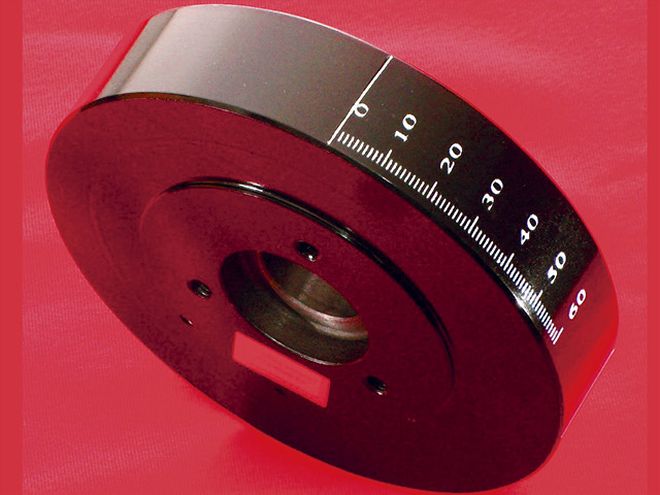 If you are building on a budget, then a damper, such as this big-block Chevy item from Professional Products, could well be what you are looking for.
Even on this basically low-powered test car, lightweight wheels had a measurable effect. Fitting them and restoring the weight by means of internal ballast showed that the reduced wheel moment of inertia alone was worth 1/3-tenth on the quarter-mile. At the end of the quarter, this translated into a lead of 4.4 feet over the baseline-spec vehicle. The reduced wheel moment of inertia plus the reduced chassis weight dropped the e.t. by a solid tenth, resulting in a 13.1-foot lead over the baseline vehicle. The last test showed it was necessary to reduce the internal ballast by 60 pounds to replicate the performance given by wheels only 36 pounds lighter. What we can say here is that weight removed from the wheels has at least 70 percent more positive effect on performance than weight removed from the sprung part of the vehicle. Extrapolating these results and applying them to a typical Detroit pony car of some 450 hp, we can say a set of three-piece Weld wheels such as shown would be equivalent to adding some 15 hp and 12.5 lb-ft to the engine's output.
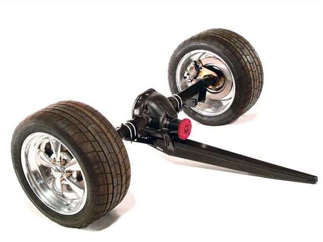 This is Maximum Motor Sport's three-link/torque-arm axle for a road-race 5.0 Mustang. It is equipped with the new forged-alloy version of the Cragar SS by Weld Racing. These wheels, which are 1.5-pounds lighter than Ford's cast Cobra wheels, are tough enough to deal with high-speed curbing during cornering. Shod with Toyo tires 1.5 inches wider than what they replaced, the wheel/tire combo is 6 pounds lighter for a 24-pound overall weight reduction.
The laws of physics that apply to acceleration also apply to deceleration. The less the unsprung mass is, the better chance the tires have of gripping the road. Also, any reduction in the moment of inertia of the rotating parts, that being principally the wheels and tires, the less energy the brakes have to dissipate.
Just before wrapping this piece up, let me say a few words on wheel choice and safety. Wheels are purpose-built. A wheel designed for drag racing can be very light because it does not have to take the kind of abuse a road-racing wheel would be subjected to. Do not under any circumstances shortchange wheel strength for the job just to get a lower moment of inertia.
Lastly, tires: Because these are at a larger radius than the wheel, they can have a bigger influence for a given weight reduction. The way to check to see if the tire you intend to purchase is heavier than some of its direct competitors is to go online at www.tirerack.com and check out the tire specs. All the weights are listed. Yes, it really is that simple.
FIG. 3 RPMHp at {{{300}}}/secHp at {{{600}}}/sec 2,2501.77.7 2,5003.48.5 2,7504.29.5 3,0004.012.0 3,2504.312.4 3,5006.014.6 3,7507.115.0 4,0007.616.8 4,2507.316.2 4,5008.517.2 4,7506.319.0 5,0006.617.1 5,2501018.0 5,5008.318.9 5,7507.718.6 6,0006.821.7 6,2504.720.2 FIG. 7 5.0 Factory Stocker HeavyLightImprovement 60 ft1.7881.7390.049 330 ft5.1145.0430.071 660 ft7.8967.8230.073 1/8 MPH88.84788.387- 0.46 1,000 ft10.33710.2490.088 1,320 ft12.3912.2890.101 1/4 MPH109.757110.3990.642 The "improvement" column shows gains everywhere for the lighter flywheel, except for speed at the eighth-mile. FIG. 7 5.0 Factory Stocker HeavyLightImprovement 60 ft1.7881.7390.049 330 ft5.1145.0430.071 660 ft7.8967.8230.073 1/8 MPH88.84788.387- 0.46 1,000 ft10.33710.2490.088 1,320 ft12.3912.2890.101 1/4 MPH109.757110.3990.642 The "improvement" column shows gains everywhere for the lighter flywheel, except for speed at the eighth-mile. FIG. 10 HEAVY WHEELS & 2,000 lbs Improvement Over BaselineFinish Line Advantage Over Baseline, in feet ET Average: 14.7303= Baseline Number MPH Average: 88.98= Baseline Number Light Wheels & 2,000 lbs ET Average: 14.69730.033 seconds4.4 ft MPH Average: 89.170.19 mph Light Wheels & 1,{{{968}}} lbs ET Average: 14.63030.1000 seconds13.1 ft MPH Average: 89.520.54 mph Heavy Wheels & 1,{{{940}}} lbs ET Average: 14.63070.0996 seconds13.1 ft MPH Average: 89.650.67 mph