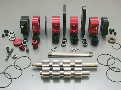
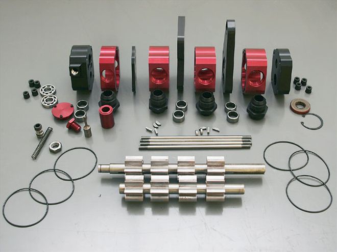
 This blow-up of an external oil pump from Fast Times Fabrication shows the four-stage design. One stage provides pressure to the engine while the other three are used to suck oil and air away from moving parts-a tremendous advantage if your rules allow a dry-sump oiling system.
When you think about race engine builders utilizing dry-sump oiling systems, it's only natural to consider the Nextel Cup guys or maybe the touring Dirt Late Model cars. After all, that's where the ultimate in power is made and the most money is being spent.
The advantages that big-budget teams derive from dry-sump oiling systems-where excess engine oil is stored in a tank away from the engine instead of in the oil pan like in a wet-sump system-are also advantages that many teams in lower racing series can use (if the rules allow). Now, manufacturers are producing systems aimed at the more budget-conscious racers. Fast Times Fabrication is one of those companies. By using readily available components and producing everything else he needs in house, owner Phil Stefanelli produces complete oiling systems designed to be both efficient and affordable.
Fast Times Fabrication isn't the only company in the racing industry that realizes cost is a factor for most of us, but the rules are pretty much the same for everyone: Precision costs money. For a Nextel Cup team trying to get every last bit of power out of an engine, the costs skyrocket. If you aren't trying to push your oiling system to the absolute limits with tolerances held to the ten-thousandths, the costs of production are significantly reduced without sacrificing reliability.
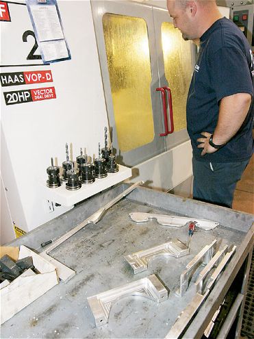 A problem with stamped-steel pans is that they flex and leak. This is unacceptable with a pan for a dry-sump system because part of the goal is to create an air-tight environment in which the pump can create a vacuum. Fast Times Fabrication uses CNC machinery in much of its building process. A technician watches the front and rear seals being cut from blocks of aluminum.
This is the first in a two-part series on selecting components for and building a dry-sump engine. The first part will focus on the characteristics of a dry-sump system, options for the engine builder, and the features you should look for in a quality product. Part two will move from fabrication to the engine builder's shop where we will discuss integrating the system into a complete engine package.
The Pan Removing the responsibility for oil storage from the pan allows it to be much more effective at reducing the power-robbing effects of windage. No matter the type of oiling system, a good circle track oil pan should include baffles to keep oil trapped near the pickup(s), adequate volume to keep oil in the pan below the reach of the crankshaft, some type of wiper, and a kick-out on the right side. The kick-out performs two roles. It increases the pan's volume without increasing depth, and allows oil to move out from directly underneath the crank. The extra area also reduces bounce-back. Bounce-back occurs when oil slings off the crank, hits the side of the pan, and bounces back onto the crank. Because of the direction the crank spins, this is only a problem on the right side of the pan. Moving the wall of the pan away from the crank with a kick-out helps reduce the problem and the windage that it creates.
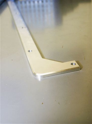 Although much of the pan is sheet aluminum, it is critical that the rails, which are the foundation for the pan and ensure a good seal to the block, stay square so they are cut from 0.250-inch stock.
A pan built specifically for a dry-sump application can include an extra set of tricks. Most importantly, by removing the pump from the interior of the pan, it creates room and allows for greater flexibility in the pickup points. Now, instead of a single pickup point in the rear of the pan, multiple pickup points can be employed in conjunction with multistage oil pumps (more on that later). Also, instead of trying to collect all the oil in one area, dry-sump pans can be sectioned so that the oil cannot slosh around in the pan or pile up in one area-in circle track racing, the rear corner at the back of the pan-and possibly come in contact with the spinning crank. Each section is drained individually by its own pickup from the oil pump.
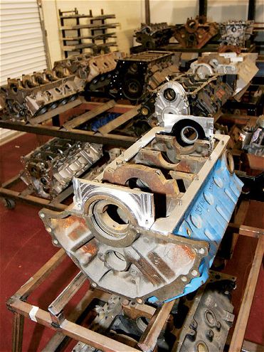 Once the seals and rails are ready, they are fitted to the specific block for which the pan is being made. Once everything is fitted properly (including bolt holes), the pieces are tack-welded and then moved to a jig.
The Pump Many of the key benefits of a dry-sump system stem directly from moving the oil pump out of the oil pan and making it a separate unit driven by a belt off the crank. Because the pump is now outside the crankcase, it is actually capable of pulling the oil out of the engine, but also the air. By creating a vacuum inside the engine, oil is pulled off engine parts more easily instead of clinging, rings seat in the pistons better, and the resistance seen by the crank as its counterweights swing through the air is basically removed.
Even a small amount of vacuum inside the crankcase can be helpful, but the engine builder must be careful to properly seal the engine from leaks using proper seals and extra care. Still, Nextel Cup engine builders are using external oil pumps to pull a vacuum as strong as 26 inches of mercury. For comparison, a perfect vacuum is 29 inches of mercury.
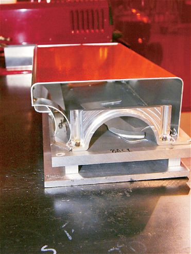 Here's our partially completed pan on a jig. The wrapper is in place, and now the rest of the pieces must be hand cut and fitted.
External oil pumps are broken into stages. Typical dry-sump systems use pumps that are between three and five stages. One stage is always used as a pressure pump. In other words, it pulls oil from the external tank and pushes it into the engine oil galleries. One stage is strong enough to provide all the pressure necessary. For racing, where excess pressure means lost horsepower, the pressure bypass is often engaged. The other stages are all used to pull oil from the engine after the oil has done its job, and also create a vacuum in the crankcase. A single suction stage can adequately pull enough oil for proper lubrication, but multiple suction stages means a smart engine builder can pull oil from different areas of the engine as well as pull greater amounts of vacuum.
For example, Fast Times Fabrication teamed with KT Engine Development to produce a dry-sump motor for a Super Late Model racer. For this engine, Fast Times built a four-stage pump, which means three stages are available to pull oil and air from the engine. Engine builder Ken Troutman used two stages to pull oil from the pan, but the third was plumbed to the lifter valley. The goal is to pull the oil used to lubricate the valvetrain directly from the lifter valley before it can drip onto the cam and crank, a major source of windage. The cam and crank are lubricated by their own oil galleries, and the "splash oiling" from the valley is unnecessary.
 Because a pan can include many welds that all must be airtight, it can take a good welder a couple of working days to finish a pan. At Fast Times, the pan remains bolted to its jig the entire time to make sure nothing moves out of position during the fabrication process.
The Oil Tank Instead of storing excess oil in the pan, a dry-sump system continually circulates oil through a large, remote tank usually installed behind the driver's seat. The tank keeps oil away from the crankshaft and provides a good method for cooling. The tank can also hold much more oil than the typical pan, which also helps to keep the engine oil cooler longer.
Valve Covers Although these aren't typically a part of the oiling system, a dry-sump with an external oil pump makes it easy to add oil squirters to the valve covers. Squirters provide a direct cooling spray of oil to the valvesprings that is much more beneficial than any splash oiling they would get otherwise. The greatest benefit from this spray of oil is it helps keep the spring cooler, which is vital because of the heat buildup endemic with the long-term high revs seen in circle track race engines. Because of the oil pump, it becomes quite simple to plumb a pair of valve covers equipped with squirters: Simply tap a line off the fitting that provides oil under pressure to the engine.
To see how all of these components come together in a race engine, check back next month for the second chapter in this series when engine builder Ken Troutman builds and dynos a Super Late Model race engine.
This pan uses two pickups, so a divider is used to break the pan into two sections. This limits oil movement in the pan and also provides some additional rigidity.
For steel pans, a screen over the pickup is possible (top), but that won't work with aluminum pans. Instead, consider using a cone screen insert (bottom) where the suction lines plug into the pan to catch any large chunks of debris before they reach the pump.
Fast Times Fabrication produces everything for its pumps in-house except for the gears. To keep prices down, the company only manufactures two section widths. The pressure stage is a 1-inch body while scavenge stages use a 1.350-inch body.
Pump gears are expensive and difficult to make, so Fast Times purchases them from Melling and modifies them to suit its needs. They are the same gears used in Melling's internal oil pumps, which makes them more affordable-and they are the seven-tooth gears, which pump better than five-tooth gears.
One feature of quality oil pumps is the use of bearings in the midplates for the shafts. Cheaper pumps use bearings only in the ends. This allows the shaft to rub against the midplates until the holes become oblong, which introduces slop.
Here's a breakaway of the pressure bypass in the pressure stage of the pump. Once the oil reaches a certain pressure, it pushes against the needle valve hard enough to compress the spring. This allows the valve to slide into the body, and oil flows past through the bypass.

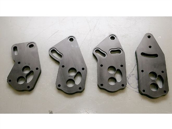
The only parts on the pump specific to a particular engine are the two midplates which also serve as mounts. From left to right are plates for a small-block Chevy, big-block Chevy, Ford small-block, and Chrysler small-block.
Each of the midplates between the suction stages have a kidney-shaped hole that allows free flow of oil through the stages. This helps even the pressure at all the pickups. Also, only one of the three suction stages has an outlet to the oil tank. This simplifies the plumbing and keeps things light. To handle the extra flow, the outlet is larger than the inlet fittings. As a general guideline, a five-stage pump should pull around 13 inches of vacuum in a small-block racing engine, while a four-stage should pull 10 inches.
Before the completed pan and oil pump are boxed up for shipping, the pan is again checked against the appropriate block to make sure everything fits as it should.
Here's a shot of the oil squirter setup in the valve covers. The oil is pumped through the aluminum tubing and squirts out in a fine spray through the holes near the rail. As you can see from the size of the holes, only a minimal amount of oil is necessary so it doesn't place an excessive demand on the pump or the engine.
Like the oil pan, the valve covers are also checked for fit and finish on a cylinder head.