News flash: No Flathead Fords came from the factory with a T5 transmission, but the Flathead/T5 combination has become an extremely popular choice for street rodders who want all the mechanical advantages of a five-speed overdrive behind their Ford Flathead.
The T5 also offers practical advantages—notably availability, affordability, and well-suited gear ratios. Introduced by Borg-Warner and later produced by TREMEC, the T5 has been around for almost 30 years, meaning that salvage yards and the Internet are loaded with specimens eager to be recruited for use in hot rod projects.
T5 hunters should be aware of the differences between "non-World Class" T5s used in S-10 pickups and the "World Class" version found in Camaros, Firebirds, and Mustangs (among other applications). For many builders, the most important difference is the shifter position: forward on the tailshaft on S-10 NWC T5s, and at the rear of the tailshaft on WC versions. That difference makes the S-10 version more favorable to many street rodders.
The aftermarket offers several ways to tie these transmissions to Flatheads. Several companies offer adapters for this application, including Wilcap Company (wilcap.com), Flat-O Products (flat-o.com), and Speedway Motors (speedwaymotors.com).
The NWC T5 installed in Mark Lopez's '33 Ford coupe is matched to a later ('49-53) Flathead with a Speedway Motors adapter (PN 916-28912). Later in this story, we'll present some details about the adapter. But first, take a look at the impressive sheetmetal fabrication, done by Ben at Stone's Metal Shop, that went into creating the custom transmission cover and floor panels.
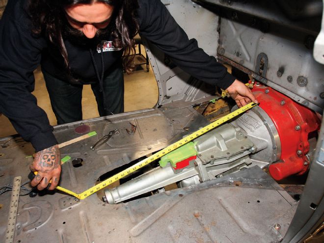
1. The Flathead engine and T5 transmission were installed when the '33 arrived at Stone's Metal Shop. The transmission was measured lengthwise from the adapter face to the end of the tailshaft to determine the length of the trans cover, in this case 33 inches. Note the Speedway Motors adapter and the forward shifter position on the NWC T5 tailshaft.
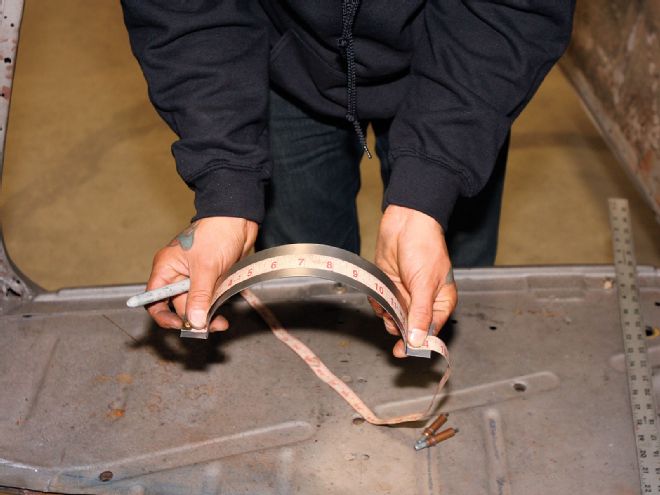
2. Strips of 18-gauge scrap sheetmetal were bent into the correct contour on the slip roll and positioned at the front and rear of the transmission to get the circumference measurements of the cover. The front measurement was 24 inches (front) and 14-1/2 inches (rear).
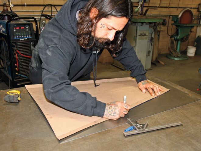
3. The dimensions were transferred to a cardboard template. An additional inch was added to both sides for the flange that will mount the cover to the existing floor.
4. The cardboard template cleared the transmission without interfering with the seat base or stealing foot room.
5. The template pattern was copied to a sheet of 16-gauge steel. The lengthwise centerline was transferred to the steel, and the piece was cut on a shear.
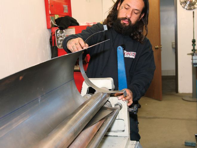
6. The rear radius is a lot tighter than the front, and forming a tapering circumference takes some talent on the slip roll. Ben adjusted the settings to create a larger circumference at the front end and a tighter circumference in the other end. The strips of scrap metal were used to determine these settings. Then, instead of feeding the sheetmetal through the slip roll, he swung out the upper die (roller) to center the sheetmetal in the slip roll, making sure the centerline was perfectly aligned with the upper die. The sheetmetal was then rolled from the centerline outward, first in one direction, then in the other. The scrap metal strip was used as a visual gauge to get the large curve correct.
7. With the circumference finished, the 1-inch flanges were bent on the sheetmetal brake.
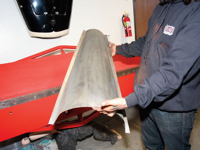
8. As expected, the steel cover fit just like the cardboard pattern. The rear portion of the cover left a crescent-shaped gap between the cover and the floor. Instead of fabricating a separate piece to finish that section, Ben decided to keep it one piece and shrink the existing piece to meet the floor.
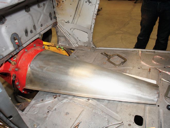
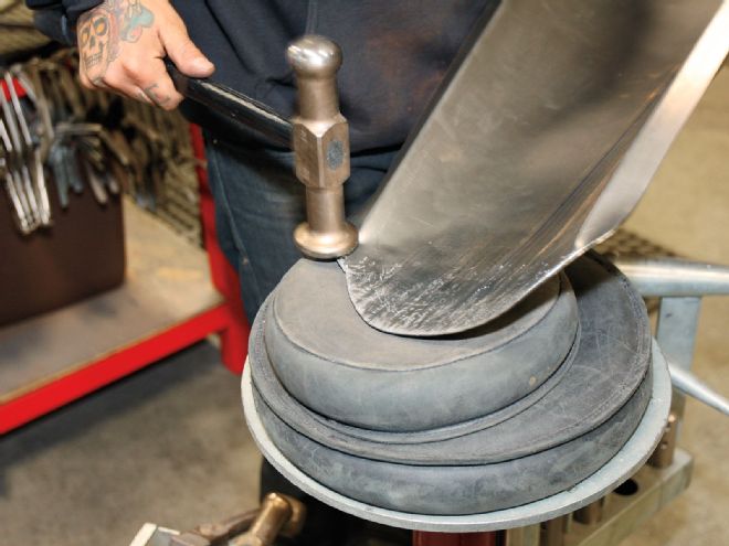
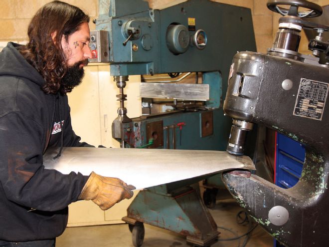
9. Using different dies on these two shrinking/stretching machines, Ben shrunk the rear portion of the cover downward.

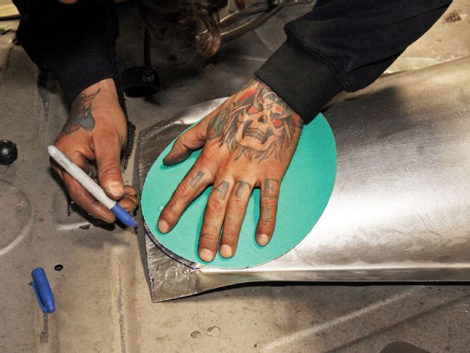
10. A sanding disc was used the mark a curved radius at the rear, which was cut with tin snips.
11-12. More metal finishing was done using a planishing hammer and a variety of hammers, dollies, and sandbags.

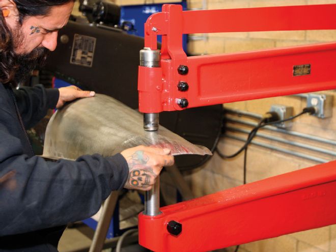
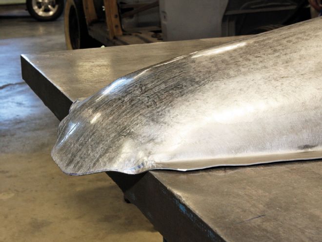
13. The end section now extended below the surface level, providing enough material for continuing the flange around the rear.
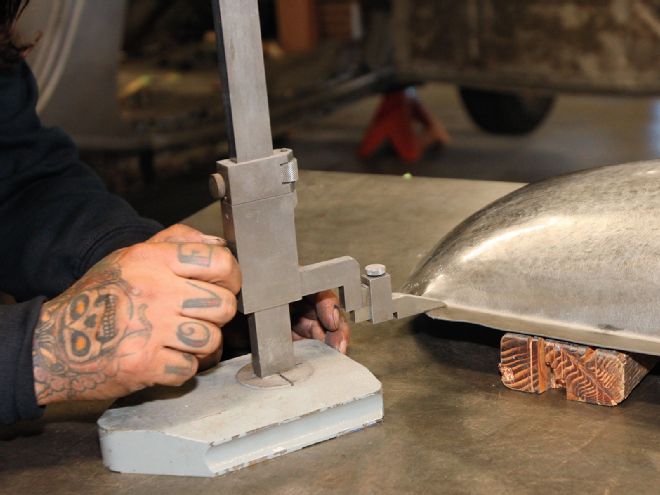
14. Ben used a height gauge scribe to mark where the flange will be formed.
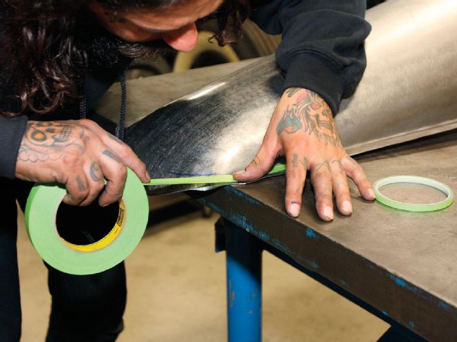
15-16. One-inch masking tape showed where to mark the edge of the flange, and the excess material was trimmed.
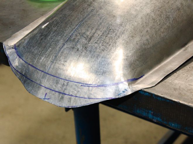
17. A bead roller created the flange around the curved contours.
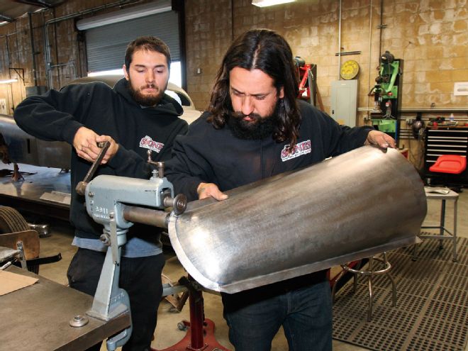
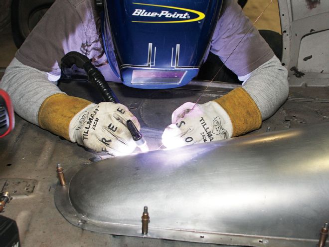
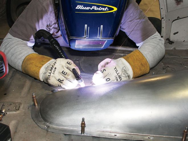
18. Even more metal finishing with the planishing hammer and hand hammers was performed to perfect the shape of the cover. The surface was smoothed with a DA sander and abrasive pads. The cover looks great—and will look even better with the rest of the floorboards in place. We'll show you that next month.
Adapting Your T5
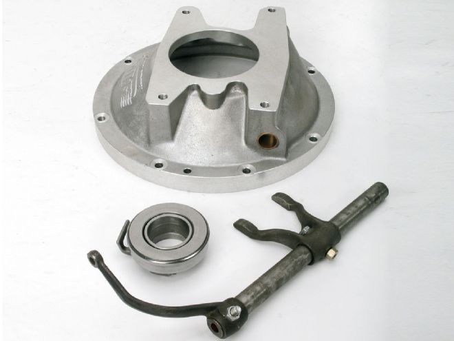
The T5 transmission in this '33 coupe uses a GM manual trans to Flathead V-8 adapter/Ford clutch from Speedway Motors (PN 916-28912). This adapter is one of several Speedway adapter styles available for this application.
1. The Speedway 916-28912 adapter allows you to retain your Ford clutch release shaft, arm, fork, and bearing. It's a great choice for applications like this '33, where an original-style chassis and pedals are being used.

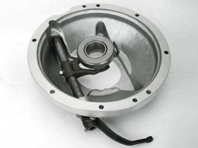
2. This is the same adapter with the components assembled.
3. Compare the 916-28912 adapter (right) to PN 916-28914 (left), which is designed for the same Flathead-to-T5 application, but for use with a GM-style pressure plate and release fork.
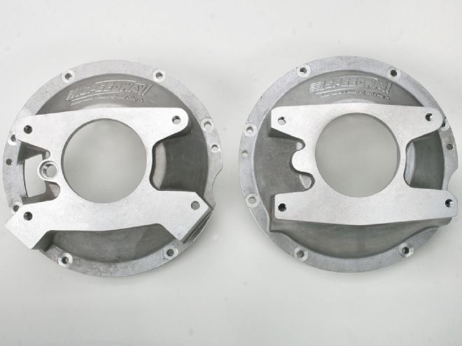
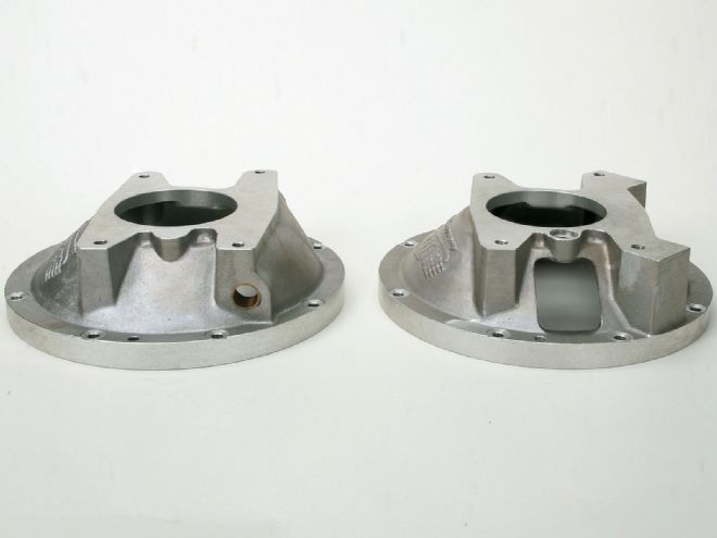
4. The 916-28914 GM-style adapter (right) features a large clutch fork window instead of the small hole on the 916-28912 Ford-style adapter.
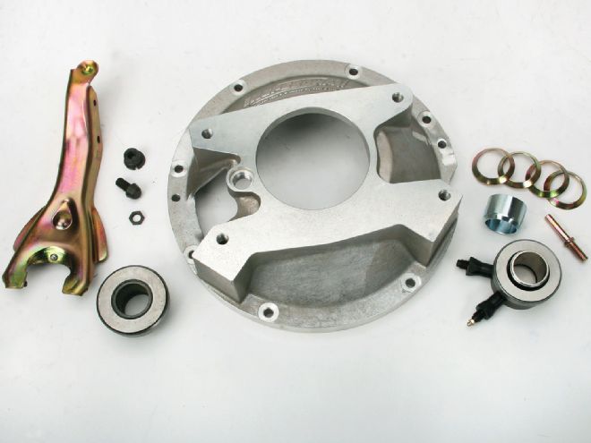
5. The 916-28914 adapter can be used with Speedway's GM-style clutch fork and release bearing assembly shown on the left (PN 916-29510) or the hydraulic throwout bearing assembly on the right (PN 910-25610). The hydraulic throwout bearing has the advantage of not requiring a mechanical means for releasing the clutch. A clutch master cylinder at the pedal, and hydraulic lines routed to the throwout bearing, can be used.
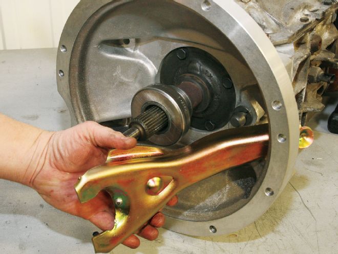
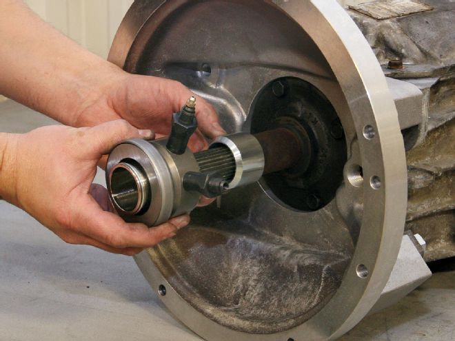
6-7. In photo 6, the clutch fork and mechanical release bearing assembly are being installed in a GM-style adapter mounted on a T5. In photo 7, the hydraulic throwout bearing and release bearing spacer are being installed.
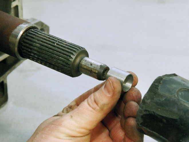
8. An adapter sleeve is installed on the T5 input shaft for any of these T5 to Flathead conversions, or Speedway can supply an adapter pilot bearing (PN 916-29520), which eliminates the need for the pilot bearing sleeve.
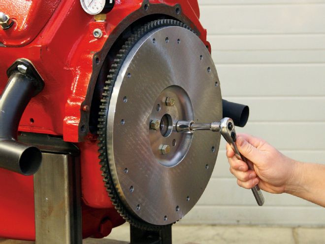
9. Flywheel choice depends on which adapter and which clutch and release assembly is being used. When using the GM-style adapter, the stock Flathead flywheel must be re-drilled to accept the GM-style diaphragm pressure plate. The alternative is to replace it with a Speedway flywheel that has the GM pressure plate pattern. This flywheel (PN 910-15629) will accept stock Ford- or GM-style pressure plates.
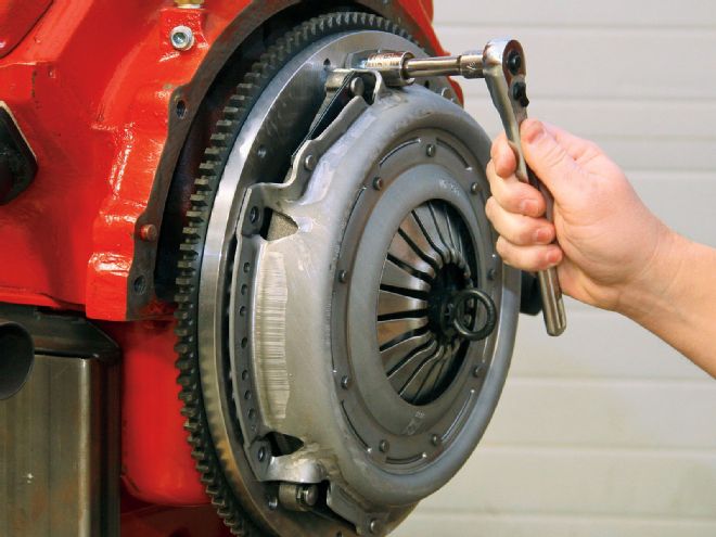
10. This 10-1/2-inch GM-style diaphragm pressure plate (PN 910-15637) and clutch disc are bolted to the flywheel. In addition to matching the flywheel and pressure plate, the clutch disc must match the transmission's input shaft spline count (14 spline on the NWC S-10-style T5, 26 spline on the WC Camaro-style T5).
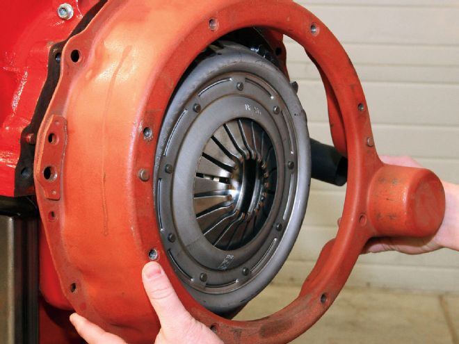
11. On early Flatheads, the bellhousing was cast into the block. After 1948, Ford used a separate bellhousing. Using Speedway's 916-28912 or 916-28914 adapter on a later Flathead requires the use of either a cast-iron Ford bellhousing from a '48-52 pickup application, or a stamped steel '49-50 Mercury bellhousing (as shown here). A matching starter plate or cover assembly is also required for mounting the starter and protecting the flywheel.
