
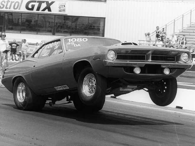
For many, building 500 horses isn't a problem; figure out what pieces will create the best possible combination, prep as needed, and bolt it together. However, once this is done, that power will need to travel through a variety of components before causing the rear wheels to propel the car forward. If you're using an automatic transmission, one of the key components is the fluid coupling between the engine and the transmission known as a torque converter.
The creation of a race converter normally begins with a junkyard core. The smaller ones come from four-cylinder cars. The housing is cut open and, if it passes inspection, the impeller/rear cover and front cover (where the converter attaches to the flywheel) are strengthened by welding on steel anti-ballooning plates to the center circumference. The vane, or blade angle ends, may be rebent for better fluid direction and rewelded for strength. A more positive angle will increase the impeller's efficiency by better directing the fluid into the turbine while allowing it to spin more easily for less slippage (static or negative angles built into the stock versions were more for smooth, non-shocking performance, but are actually higher-stalling due to their inefficiency). These pieces will then be sent to a furnace for complete brazing. An aftermarket stator with its one-way roller sprag will be installed for better strength, fluid dynamics, and torque multiplication. The flexplate mounting pads are attached to the front cover, and the rear or top cover, and snout are welded to enclose the assembly, and for Chrysler cars, the starter ring gear is attached.
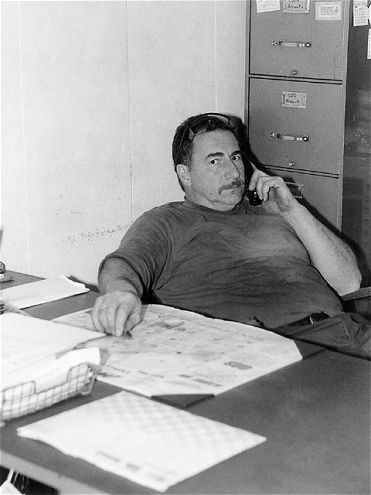 Frank Lupo of Dynamic Racing Converters knows racing. When he's not at his desk on the phone with customers, he races his Super Stock Hemi 'Cuda in NHRA competition.
But how about in the real world? How do you know which converter will work for your car? We recently had a chance to sit down and talk with Frank Lupo at Dynamic Converter and Pro-formance Transmissions in Newark, Delaware. Lupo is a leading manufacturer of converters and a Mopar racer to boot; his NHRA Division 1 Hemi Super Stock cars are well known. We asked him to define the single-most important thing in selecting a converter for street/strip use.
"The first and most important thing you can do before making a converter purchase is to be realistic about what the car will be doing. There are always going to be compromises between performance and streetability. Durability is just as critical on a street car as on a drag car. Efficiency, how much the converter slips, is another factor, and, of course, with street cars, driveability comes into the decision. Personally, I'm a big proponent of not having enough converter on the street rather than too much."
There are any number of factors that can play into the converter selection, and Frank recommends that you talk with a knowledgeable builder when making this decision; it isn't a simple guess. Things that play into the selection can include usage, horsepower/ torque curves, car weight, rear gear (and transmission) ratios, and more. Frank says the more information you can give about the car, the easier it is to match the converter to the package.
"I want to know everything I can, because if I'm supposed to be building a converter to stall at, say, 5,500 rpm, and I don't know the collector size, the cam's lobe separation, the type of fuel (gas or alcohol) and other details, I'm stuck guessing. With these changes in the combination, that same converter might stall at over 6,000 rpm. I would much rather know ahead of time what I'm going to need than get a phone call later saying it doesn't work like I thought it should. There's an infinite number of variables, and each will have a bearing on how we construct that converter."
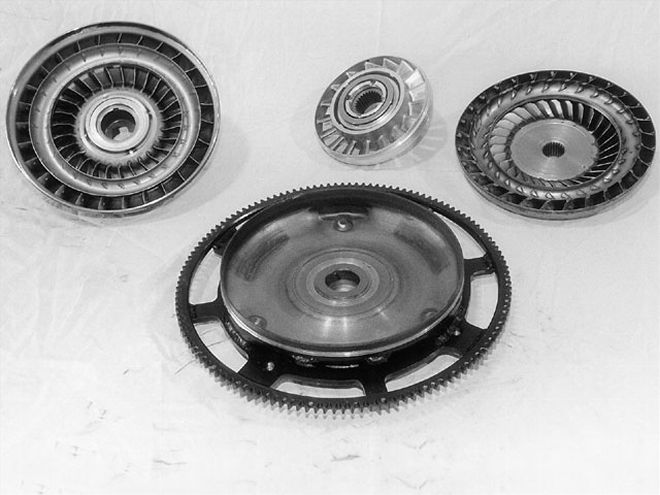 Here are the basic components in a performance torque converter. In the foreground is the Mopar starter gear/front cover. The turbine, splined for the input shaft, is at the upper right; it rides on the front cover. The stator (upper center) goes in the middle, and the impeller/rear cover assembly with the slip yoke for the transmission is at the upper left.
The next factor would be construction quality. You can buy converters from a variety of sources and in a variety of price ranges, but this is an area where generally you get what you pay for. A converter whose rebuilding process has been sloppy will result in poor performance and short life; in a high-horsepower environment, this is where you find out who did it right when the bad converter breaks. Prices are based on the level of modification for the most part, and time is money. Frank is honest to note that there are several companies capable of providing high-quality converters and components in addition to Dynamic. If you can afford the higher-priced converter, you'll be better off.
"For example, using a 9 1/2-inch unit with the more efficient positive blade adjustment angle will almost always be better than getting a 10- or 10 1/2-inch converter with negative angle," says Frank. "The smaller converter will give measurably increased performance on the track and yet be more efficient on the street. This is due to the fact that, though the converter is smaller and higher stalling, by using a positive blade angle, the fluid is directed off of the blades without having to overcome the negative angle. The smaller converter also has less reciprocal mass, meaning less energy is required to get it moving and it also won't build up heat as quickly. The positive angle adjustment is a process that involves actually bending one end of each blade upward; this is done by hand and requires skill and patience, hence the higher-end cost."
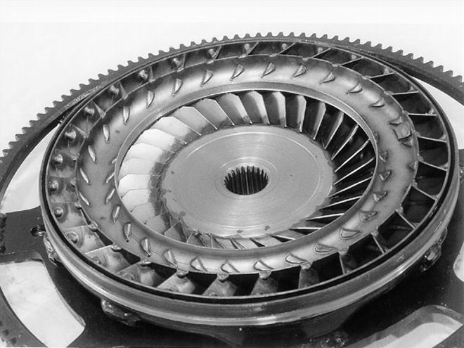 The turbine rides inside the front cover. Note the amount of welding that has gone into the vanes. The positive angle bent is seen on the outside edges, allowing a smaller converter to operate more efficiently. The large steel area surrounding the input shaft splines is the anti-ballooning plate.
Another primary factor when thinking about selection is rear gearing. The higher-numerical gears obviously will give you an advantage in moving the car forward, so a given converter's stall speed will actually be less with a 4.10 gear than if it were sending power to a 3.23 gear. This is why stall numbers are more of an estimated than exact science; a car with the higher 4.10 gear will stall a converter quicker than than one which is slower to transfer power to the back tires. The 3.23 car will also put more load on the converter since it's not moving the mass as easily as the 4.10 gear, and if the converter is too loose (higher stalling), it will slip excessively in street applications.
Car weight plays a role as well, and for drag cars, aerodynamics become a factor at high speeds. Take two cars for example. One is a B-Body with a full interior, the other is an A-Body with some lightening; they have an estimated weight difference of 500 pounds. You have a driveline consisting of a 440 that makes 375 horses, a standard-ratio 7.27, and a 3.73 rear gear. To make that engine work efficiently on the street and strip, the converter will require additional stall in the lighter car, since, like the rear gear ratio, it's easier for the car to move forward. Also, since the B-Body is heavier, slippage will be greater in that application, meaning heat again becomes a real factor. A larger, more-effective-at-lower-rpm converter would be a better choice.
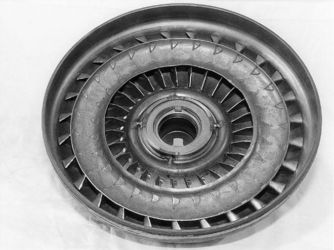 This impeller has also been modified for more flow, with the vane angle ends turned in to accelerate the fluid into the turbine.
For many, the best solution is to have a converter built specifically to fit your combination. When doing this, even more data is needed, such as exact cam specs, cylinder pressure, race weight, head modifications, carb specs, and more. For an all-out drag car, Frank recommends that the stall speed be built for 1,500 rpm below the shift points, which will be based on the horsepower your engine makes. The way the engine makes that rpm is important as well. Does the horsepower peak come and go quickly, or is it a wider powerband? For a dragster with a balanced engine using rollerized internals, a high-stall, fast-reacting converter will be the choice since the car will be used only for racing and that motor can likely get rpm up very quickly. A street/strip door car with the same engine will lose some efficiency since it's heavier and will also lose driveability due to slippage; the converter on this car should be tighter (stall lower) to compromise between the two types of use. This car, which is in the 3,000-3,400-pound range, should stall at 2,000 rpm below the shift points. For a 3,800-pound restoration, a standard rebuild may be sufficient, but Frank notes that positive blade angles in a smaller converter will allow for a higher stall plus increased mileage, since the converter is constructed for more efficient fluid flow. The converter in this car should stall 2,500-plus rpm below the shift points since it will see very little, if any, track time. Frank tends to put less stall into street converters because "most guys drive more on the street than they care to tell you on the phone!"
For stroker engines pumping out 500 inches, Frank states that he still goes with a 9-inch converter rather than the 8-inch, even if the car is strictly for drag racing. Most stroker motors are not big rpm engines, and the larger converter with its reduced slippage will keep the rpm range lower, especially in the speed traps where the engine is maxing out. Unless you want to replace connecting rods and other parts, it's better to save the wear on the motor and give up some 60-foot time than going to a converter that's too small. Moreover, a larger converter will allow the car to hook up on a marginal track surface since the torque multiplication isn't as great. In a street car, the larger unit will also hold more fluid and, therefore, run cooler. Conversely, a bracket car may want more stall if only because atmospheric changes have less impact at higher rpm levels, making the car consistent. Indeed, higher stall converters are often used by racers in areas that are at higher elevations.
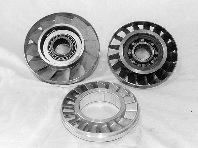 A selection of stators shows the wide variety of vane construction and design, all which will play into the stall speed of the converter. The two rear examples have the one-way roller clutch consisting of inner and outer races installed.
Regardless of application, Dynamic uses a billet stator in place of a cast unit, and Frank showed us some new-age sprag components that are very small yet strong. The smaller the converter, the more serious the reinforcing must be; larger anti-ballooning plates and heavier welding are required. The smaller converter will also be more expensive because cores are harder to obtain. The old Opel and Vega cores used in the 8-inch converters are used up, and many later stock converters are not constructed with the same steel quality, meaning more reworking. The bottom line is to realize what your combination will need based on its mechanical construction coupled to its intended use.
"In my opinion, converters should be overbuilt," states Frank in conclusion. "The quality and time that a good company spends to create a converter really translates into less time spent tearing down the car to return and replace an average one when, not if, it breaks. The goal is to make and sell a converter that will last, to give the customer something he can count on when he's out on the starting line."
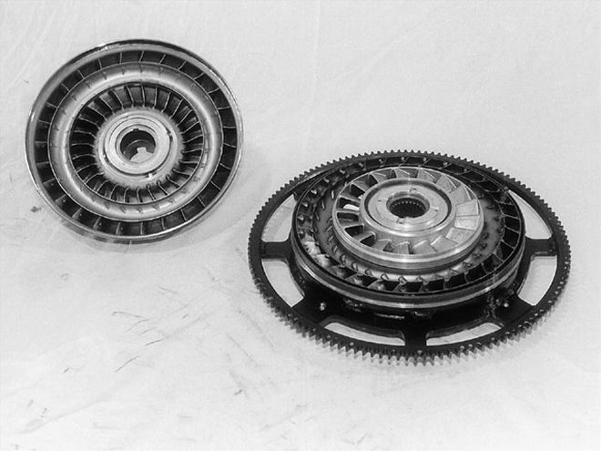 The stator rides inside the turbine (thrust washers separate the pieces) and the impeller, which is also the rear cover and transmission snout, will be welded to the back cover to seal up the unit.
Just How Does This Thing Work?
Torque converters are something of a mystery for most of us. What's basically happening inside is fluid (and fluid alone) is converting that 500 horses and applying it to the back tires; there is no direct mechanical connection. The converter assembly is inside a circular housing that can be bolted or welded to the starter ring, which is, in turn, bolted to the flexplate and the crankshaft. Meanwhile, the transmission's input shaft is spline-fit to a floating turbine inside the housing that won't turn if there is no fluid. This turbine moves only when transmission fluid is thrown off by centrifugal force from a similar-appearing piece called the impeller assembly. As the impeller spins with the engine rpm, steel vanes, or blades, are directing and angling fluid outward in a clockwise direction. This fluid will be pushed toward the outside edge of the impeller assembly and forced into the turbine.
The vanes in the turbine are similar to the impeller, but are reversed to direct the fluid inward counterclockwise and, in turn, cause the turbine to spin; it's this force that will begin to turn the trans input shaft. The fluid is then directed to the center again, where it's forced back into the impeller to begin its travel to the outside edge again. A half-round trough called the split ring is mounted to the center of both the impeller and turbine, which keeps turbulence down and directs the fluid; the fluid recirculates through the outer and inner sides of the assembly.
Centered between the impeller and the turbine is a smaller piece called the reactor, or stator, which serves two purposes. First, its angled vanes reverse and direct the fluid flow coming from the turbine back to the impeller, but more importantly, the stator actually increases the torque. Inside the stator is a one-way clutch unit that consists of a splined inner race, an outer race fit into the stator, and a sprag, or roller clutch, separating the two. The inner race is spline-fit to a fixed support on the transmission's front pump and cannot turn; the stator rotates in just one direction because of the clutch rollers.
How does it work?
At idle, the impeller begins spinning fluid into the turbine, which, in turn, pushes it back through the stator, which is locked by the roller sprag. Once it reaches a certain fluid pressure level, the stationary stator vanes actually create vortex flow, slingshooting fluid at an ever-faster rate back into the impeller. In fact, the impeller efficiency is almost doubled as this centrifugally charged fluid is pushed into it, multiplying torque and spinning the turbine harder. All of this happens instantly as the engine rpm begins to increase, when you hit the throttle. Stall occurs until the turbine reacts to this torque multiplication and catches up to the impeller. Once the turbine and impeller are close to the same speed, the sprag will unlock and let the impeller, stator, and turbine turn together and work as a single transfer unit.
Now, what about stall speed? This is the speed at which the turbine overcomes its resistance and turns the input shaft. As the impeller spins, the turbine begins rotating but must overcome the resistance of the driveline. As the stator continues to accelerate the fluid, the impeller finally creates enough pressure to get the turbine/ input shaft to rotate. Stall speed is the engine rpm level at which this event occurs.
If the converter measures 15 inches in diameter, the impeller would need to spin only to a low, say, 1,000 rpm before the car would begin to move slowly. However, a 7 1/2-inch converter in the same car might need to spin to 5,000 rpm before the car moves, because that little unit needs to overcome the resistance before it will accelerate the car. Artificial resistance can be created through a trans brake, making the impeller spin higher against the locked driveline. In addition to increasing or decreasing the physical size of the converter, the builder even more closely regulates the desired stall speed by adjusting the stator's sprag spring strength and vane angles in the impeller, stator, and turbine.
A stock converter's vanes are normally static, or vertical, when assembled. The builder can create a negative angle to increase stall and resistance by bending vanes forward so the fluid has to work harder to get the turbine to spin. Therefore, say a 10-inch converter that stalls stock at 2,400 rpm can be made to stall at 3,400 rpm. The blade angle can be bent in the opposite direction so the converter becomes more efficient.
The trade-offs are driveability and heat. The faster the fluid is spun in the converter, the hotter it gets. Even though it's transferred through the front pump of the transmission and interchanged with the fluid in the transmission so it's "fresh," this is why an aftermarket transmission cooler is very important on performance cars with high-stalling converters. Moreover, a high-quality fluid is mandatory to ensure it doesn't burn due to the increased heat (some synthetics are now good to temperatures above 400 degrees Fahrenheit, and will give additional stall to boot). Heat is the most common factor for transmission failures, as the fluid breaks down when it's overheated and loses its hydraulic optimum.
Driveability suffers as the converter slips when there isn't enough rpm and fluid force to turn the turbine effectively; the impeller is spinning, but not hard enough to allow the turbine to spin at the same rate. Therefore, the fluid is taking the brunt of the horsepower and creating, you guessed it, heat. If the converter stalls at 3,200 rpm and you're driving at 2,200, the car may be moving, but a lot of energy is going right to the liquid in the form of heat and the stator remains locked. All converters will slip to some extent. The higher the stall, the more slippage, so there's often a trade-off in mph with a given combination when going to a higher-stalling unit.