Imagine a turbocharger trying to pressurize a carburetor with its small venturis and finicky floats and you can get some idea why electronic fuel injection opened the door to big boost, big power, big reliability, big fuel economy and a cleaner burn. Some of the more prominent early beneficiaries of the marriage of turbos and EFI include the '86 and '87 Buick Grand National, the '84 to '87 Z31 300ZX Turbo, '84 to '89 Mitsubishi Starion ESI-R and '87 to '92 Mark III Supra Turbo. These 'founding fathers' laid the foundation for the prodigious power production we see in today's factory turbocharged offerings. The accompanying power-per-liter chart tells the tale:
 |
Electronic Fuel Injection, MAF and MAP Sensors - EFI Basics Tech
The basic EFI set-up has remained fairly unchanged through the years. However, the precision and speed of the sensors and computers (hardware and software) have improved with the times, as has the programming prowess of the OEs and the aftermarket alike, hence the big numbers. Electronic fuel injection consists of an ECU that makes fuel and ignition tuning decisions based on input received by a variety of sensors.
MAF vs. MAP
The headline sensor in a Mass Air or Mass Flow type of EFI system is the Mass Air Flow (MAF) sensor. The other popular type of EFI system, Speed Density, features a Manifold Absolute Pressure (MAP) sensor as its frontline warrior.
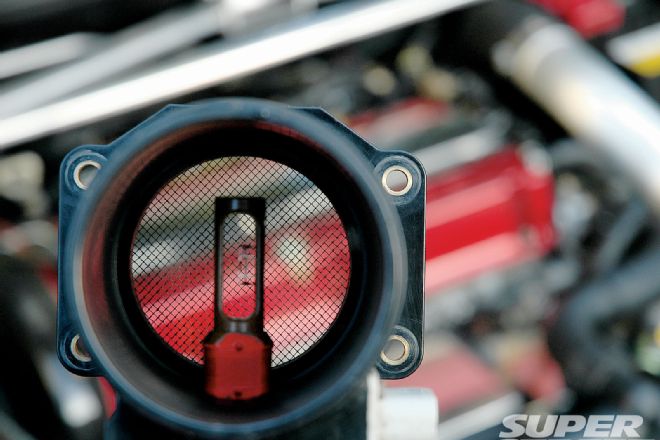
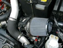
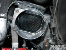
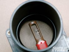
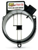
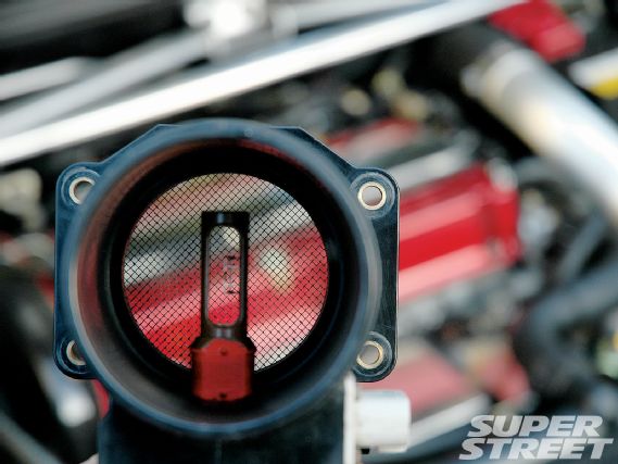
A Mass Air Flow sensor is usually mounted near the air filter box or somewhere before the throttle. It meters the amount of air going into the engine. There are two different types of Mass Air Flow sensors: Hot Wire and Vane Meter.
A Hot Wire design, the predominant MAF sensor in use today, places an electrically-charged hot wire in the air stream and the sensor reads changes in the resistance of the wire brought on by the temperature/density of the air flowing past it. The sensor tries to compensate for the resistance in the hot wire and keep the resistance constant. During the act of rebalancing, the resistance is converted into a voltage signal of between 0 and 5 volts and sent to the ECU.
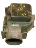
The Vane Meter uses a flapper door contraption that is lightly spring-loaded. As the air comes into the engine the movement of the flapper generates the 0 to 5 volt signal that is forwarded to the ECU. The drawback of this sensor is its potential as a restriction as air volume is increased, i.e. turning up the boost. This type of sensor has been out of fashion for sometime.
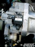
A Manifold Absolute Pressure sensor is an entirely different beast used in a speed density set-up. It does not meter flow; it is basically a pressure meter that converts the vacuum or pressure in the manifold into a signal that the ECU can use in accordance with other sensor inputs to make tuning adjustments.
The Supporting Cast
While all sensors perform an important job, the Throttle Position Sensor (TPS) has a profound effect on the operation of any EFI system. It's a rotary style sensor that has a voltage for idle, zero throttle and wide-open, 100-percent throttle. It forwards this voltage that represents the percentage of throttle opening to the ECU. The TPS is also able to interpolate the speed or rate in which throttle position is being changed from moment to moment, which then allows the ECU to 'predict' future fuel/ignition events.
The ever-important Oxygen Sensor provides a scorecard or report card to the ECU. It is placed on the exhaust side, usually in the header, where it measures the amount of oxygen in the exhaust gases. The data is used to determine the air/fuel ratio so the computer can lengthen the pulse duration when too much is present and more efficiently burns the air/fuel mixture. It should be noted that this occurrence is more for catalytic converter efficiency than an eye-opening power gain.
Air density is impacted by air temperature. The Air Temperature Sensor is the MAF's sidekick, offering further insight into the quality of the air coming into the engine. The MAF does most of the work and the air temperature sensor provides fine tuning data.
 |
Electronic Fuel Injection, MAF and MAP Sensors - EFI Basics Tech
A Coolant Temperature Sensor plays a key roll in engine start up and the engine's performance before it reaches its optimum operating temperature. It mostly controls the amount of fuel used during and after start-up.
The Atmospheric Pressure Sensor is basically an onboard barometer informing the ECU of its elevation. This data is used as part of the air density equation and allows the engine to run more efficiently in a place that's much higher up above sea level, like Denver, Colorado.
A Tach Sending Sensor taps into the voltage coming of the coil. The pulses are converted to illustrate the engine speed in the ECU. Engine speed is a key element in every calculation the ECU makes.
Mass Air vs. Speed Density
Both systems do the same thing but go about their missions in a different way. A mass air set-up is much more agile than a speed density system in that it meters the air via the Mass Air Flow sensor (MAF), and, using input from the sensors at its disposal, makes tuning adjustments in open loop operation based on the input it receives. At WOT, the system goes into closed loop operation and makes its decisions with fewer sensor inputs. The mass air system uses an algorithm to devise its tuning changes so it can compensate for most power adders.
Conversely, a speed density system plots its air/fuel ratio and ignition curves on pre-conceived maps. It doesn't not meter air but uses a Manifold Absolute Pressure sensor (MAP) to compensate for altitude and ambient air temperature that the ECU uses to calculate air mass. Rather than plotting its tune in open loop, a speed-density ECU takes in its sensor signals and selects a pre-programmed map. For instance, at WOT it employs Map 53, then it sees some changes and moves to Map 27 and so on. The shortcoming of the speed density approach is its inherent inability to react to changes in airflow/volumetric efficiency of the engine brought about by some more aggressive power adders' forced induction for sure, but a battery of hard hitting bolt-ons can jump beyond the speed density system's ability to compensate. To accommodate said power adders, the computer will need to be diligently reprogrammed and in boosted situations, positive air pressure conditions will need to be addressed.
Some popular speed density applications include '92-'95 Civics, Chevy LT1s and other Tuned Port Injection creations from GM. The mass air camp is represented by the classic Nissan Sentra SE-Rs, '90 and up Z-Cars, Toyota 2JZ Supras, Evos and WRXs.
Whether its mass air or speed density if you are planning to modify the engine by way of forced induction, a competent understanding of the sensor array and inner workings of an EFI system will certainly prove beneficial. When the time comes to select a tuning scheme for you, new combination, you and your performance shop will be speaking the same language.
POWER BY DISPLACEMENT CAR OUTPUT HP/LITER Mitsubishi Evo IX 143.0 Pontiac Solstice 130.0 Subaru WRX STI 117.2 Mazdaspeed3 114.0 Honda S2000 AP2 109.1 Mini Cooper S 107.2
