Shock absorbers, as the name implies, work with the truck’s suspension to absorb the effects of bumps and holes in the road. They help damp the impact and vibration during driving while also making sure the tires are always in contact with the ground. Damping vibration and impact may seem like an easy enough concept to grasp, but there are three important energy principles to consider, too:
Kinetic Energy: Energy which is in motion (in this application it refers to the up-and-down movement of the truck tire due to variations of the surface of the road or trail)
Elastic Potential Energy: Potential energy of an elastic system (leaf and coil springs and torsion bars in this case) that is deformed under tension or compression
Law of Conservation of Energy: Energy cannot be created or destroyed; it can only be transformed from one state to another. In mechanics, conservation of energy is usually stated as E = T + V, where T is kinetic energy and V is potential energy.

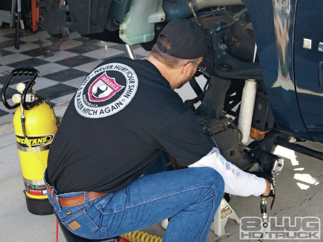
| This is what the installation looks like when completed.
A shock absorber’s sole purpose is to damp the compression and rebound of a suspension system by controlling the speed at which the suspension cycles. Without them, every obstacle the tire encountered would result in the truck bounding up and down until the kinetic energy is dissipated as heat and the elastic potential energy of the spring is reset. Without the shock absorber, your truck would handle like a playground spring rider: fun for a toddler—dangerous for a truck. Like a strict teacher on playground duty, the shock absorber uses the law of conservation of energy to keep things safe. First the shock slows the suspension’s cycling of compression and rebound. Because energy cannot be created or destroyed, the shock transforms the kinetic energy to heat as it damps the movement of the springs.
Engineering
Shock absorbers work on the principle of fluid displacement and convective heat transfer. Forcing a piston through oil, shocks develop the hydraulic friction necessary to oppose the unwanted bounce in the suspension. Hydraulic fluid in the shock body is forced through orifices in the piston head as it compresses and rebounds. The orifices meter the amount of fluid through the piston, which slows down the spring movement, thus creating a velocity- sensitive damping device. This means the faster a suspension cycles, the more resistance the shock absorbers provide. Consider a screen door: It opens with a slow and steady pull, but try to jerk it open with a hard and fast pull and you’ll discover it’s not so easy anymore. Most of these screen doors employ a basic mono or twin-tube shock absorber for door-closing duties.
Most OEM shock absorbers are of the twin-tube variety, much like the one in the screen door example. This type of shock is perfectly acceptable for street use, but it does have limitations and drawbacks. The primary disadvantage is that when it is asked to endure heavier loads than designed for or sustained rough terrain it will overheat and aerate. When the oil in the shock foams due to excessive heat generation, the shock will lose its ability to damp, creating a bouncy and scary ride. So if you find yourself driving on the trail at more than 25 mph, have added larger tires and rims, and do a lot of daily driving, you may want to consider upgrading your shocks to some with remote reservoirs. Reservoir shock absorbers offer many of the same benefits and features as monotube shocks, but with a few extra twists. Built with an added fluid reservoir, these shocks offer less cavitation with enhanced cooling ability. Essentially, these shocks will maintain excellent performance for extended periods, even in hard-core off-road situations. As an added bonus, nothing beats the look of reservoir shocks. So now you know how remote reservoir shocks work and why you need them.
Introducing the 5160 Remote Reservoir Shock
The 5160 remote reservoir shock absorber is the newest addition to Bilstein’s shock lineup. The 5160 remote reservoir shock brings race technology to your truck in a bolt-on package. The 5160 shock features a monotube pressurized gas design with finely tuned valving, increased shaft travel, and a remote reservoir. Bilstein’s patented digressive valving provides exceptional handling and control regardless of the driving conditions. The Bilstein 5160 line of shocks uses a dividing piston located in the reservoir rather than the shock body to provide more movement for the shock piston and more wheel travel than traditional shocks, which have the dividing piston located in the shock body. Moving the dividing piston to the remote reservoir not only increases piston travel but also provides extra fluid and gas capacity for improved heat dissipation. This enables the 5160 remote reservoir shocks to improve the two basic functions of a shock absorber, namely damping and heat dissipation. The shocks also feature a 46mm piston attached to a case-hardened, hard-chromed and polished 14mm shaft. And it’s all housed in Bilstein’s Triple-C technology finish, which is not only good looking but is designed to withstand harsh environments for years to come.

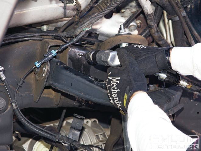
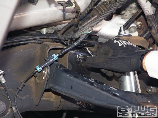
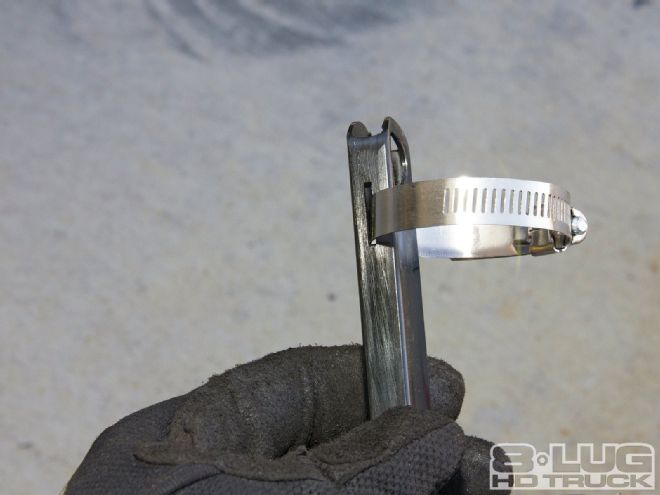
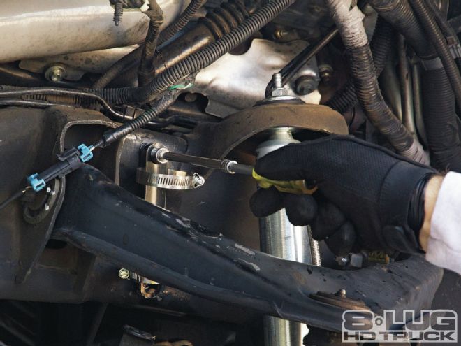
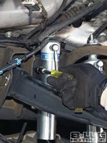
| The swivel hose allows for a variety of installation options for the remote reservoir, including next to the main shock (using the optional billet reservoir clamps).
How to Drill and Tap a Hole
Drilling and tapping a hole in metal is a simple process that can be accomplished with handtools. If it is performed correctly, it can yield a structurally sound threaded connection. The size of the drill bit is the single most crucial factor in determining the strength of the hole. An oversized drill bit will create a loose connection between the threads of the bolt and the threaded hole. A drill bit that’s too small will result in a broken tap or binding between the bolt and the threaded hole.
1. Mark the location of the threaded hole with a center punch.
2. Using a drill and tap chart, select the correct drill size for the required bolt hole.
3. To preserve the cutting edge of the drill bit, use cutting fluid to keep the drill bit cool while drilling.
4. Install the tap into the T-handle and coat the tap and hole with more cutting fluid. Keep the tap perpendicular to the hole. Turn the T-handle clockwise to begin tapping the hole.
5. After each 360-degree revolution of the T-handle, turn the T-handle counterclockwise ¼ turn to prevent material bind and the possible breakage of the tap. Keep applying cutting fluid throughout the tapping process.
6. Reverse the tap to remove it from the threaded hole. If needed, use a grinder or file to remove any burs from the hole.
