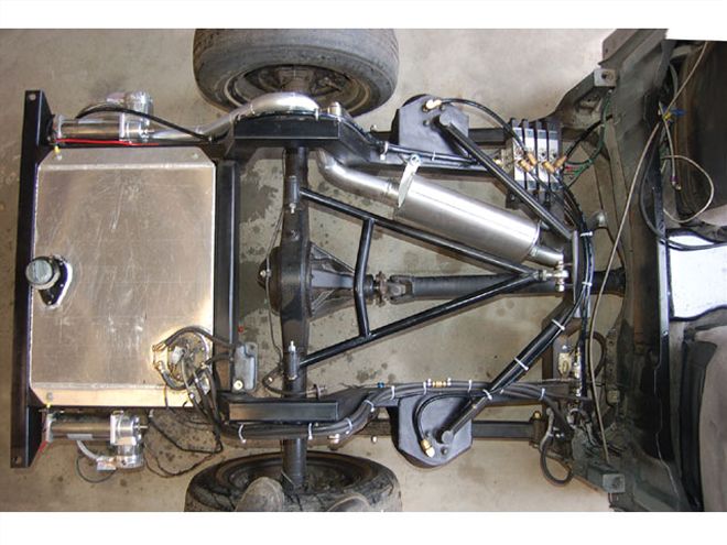
| rear Suspension Design rear Suspension
There are many ways to lower a truck, and the options multiply with rear suspension design-especially when you're dealing with an adjustable suspension with airbags or hydraulic cylinders. One only has to walk among the rows of lowered trucks at any show and peek through the holes in the bed floors to see the plethora of ways to make the rear axle of a truck cycle up and down. If you have ever wondered which linked suspension design is right for your truck and the type of driving you intend to do with it, this article will provide not only the answer but also a good definition of how a suspension should work. By the time you're done reading, you'll be able to pick a rear suspension design that will offer a good compromise between ride quality, traction, handling, and of course, getting your truck flat on the ground.
Suspension Designs
Three- and Four-LinksWe've grouped these together because they are essentially identical when viewed from the side. The names are indicative of their designs: a three-link has three links, and a four-link has four links (the Panhard bar or Watt's links are not counted.) These link systems can be configured to excel at just about anything you want your truck to do, whether it's road racing, drag racing, off-roading, towing, cruising, or hopping. If properly designed, these systems present few pinion-angle changes or driveshaft "plunge" issues, which can be a big deal when trying to get the most usable travel out of your rear suspension.
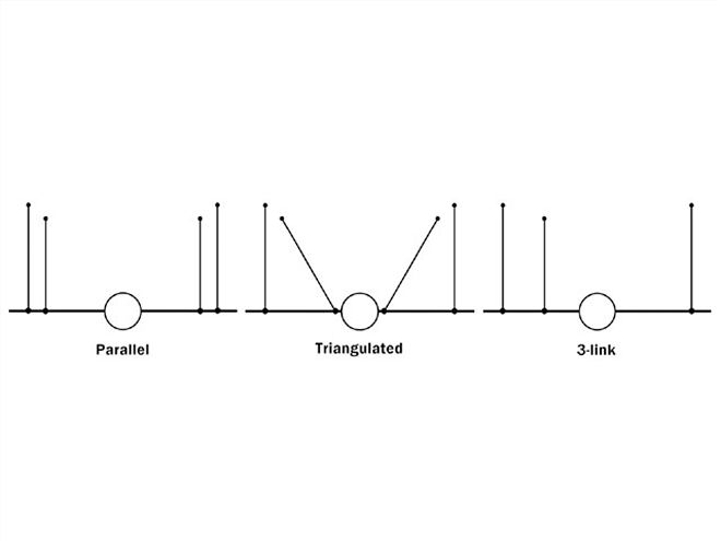
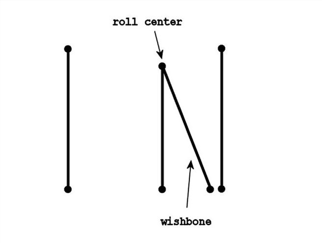
A different type of link system that falls into the three- and four-link group is the wishbone three-link. It is basically a triangulated four-link in which the triangulated bars are joined together to form a single point. Technically, however, it is still a three-link. The advantages over a traditional triangulated four-link are that the wishbone can be built much narrower and it can be oddly shaped to fit into seemingly impossible confines, with comparable lateral control.
Two-Links and Ladder BarsThese are grouped together because they are essentially the same thing: A ladder bar is merely a type of two-link suspension. This system is limited in what it can do because it typically does not offer the articulation (one wheel up and one wheel down) that is necessary for most daily-driver or performance applications.
Chevy did build trucks in the '60s and '70s with a two-link that worked (NASCAR rear suspensions are based on this design), but it was engineered/designed to do so. You see, the "truck trailing arm" two-link has the forward frame mounts right next to each other with only enough room for a driveshaft to fit in between. These narrow mounting points allow the rearend to move more with just bushing flex alone, and on top of that the bars are actually engineered to allow some twist. This gives the design limited articulation. So, to properly set up a two-link that offers the articulation desirable in a street application, you'd have to take into consideration the design attributes of the Chevy truck system, which aren't easy to recreate.
Two-links installed on today's trucks are not as capable as GM's version. The traditional two-link also has travel limitations because of pinion-angle issues. Theoretically, the rearend should not rotate as it runs through its travel (it is necessary for it to, in order to have an instant center, but only a small amount), and a two-link forces it to rotate around a single point set by the length of the links themselves. This is not a big issue if the bars are long enough with a limited amount of travel, but it's a weakness just the same. The major issue is its inability to articulate.
For simplicity's sake, we used a ladder bar in the roll-steer diagram on p. 107. Look closely and you'll notice that as the suspension cycles though its travel, the rearend housing rotates around the single front pivot point. As the suspension travels up it rotates forward, and as it travels down it rotates back. You can begin to understand how having one wheel up and one wheel down can be an issue. Essentially, on a two-link/ladder-bar system, the rearend housing acts as an antisway bar-a really big antisway bar-and that is not desirable for good handling or even daily driving.
| FIGURE 1
Full Reverse and two-Forward/two-Reverse Link SystemsIf all you're looking for is simplicity of installation and you don't want a two-link, these systems are the ticket. We have all seen them at shows or on the road (you might even own one!), so we can't argue that they don't work. The best explanation that we've been able to come up with for these systems is that they are counterproductive. The suspension's job is to take energy that is being transferred into the tires from the ground and to properly transmit those forces into the chassis to be used to create more traction. A reverse link system, in which the bars mount to the rear axle and the rear of the chassis behind it, does just the opposite, and the two-forward/two-reverse link system is nearly unpredictable in how it transfers energy from the ground to the chassis.
Even if you calculate every single point to an exact placement when designing one of these systems for your truck, you will still only end up with a driveable truck and not one that handles properly. Your only hope for performance with a reverse triangulated four-link is to limit the travel as much as possible and run a stiff spring and a stiff shock. Then, maybe you'll have the traction of a poorly set-up forward-facing link system. The best way to think about it is to understand that with a properly designed forward-link system the rearend is actually being pushed against the ground by the chassis. So any force that the rearend can use to push against the chassis will ultimately create more traction. With a reverse-link system, if the rearend were to pull down on the chassis there would be an equal loss of traction. Try this on a bathroom scale. Stand on the scale in front of a cabinet and pull up on the cabinet and see that your weight goes up according to how much force you are able to apply to the cabinet. Now push down on the cabinet. Your weight will go down to nothing fairly easily. That is what's happening on a reverse-link system. The rotating force of the tires driving the truck forward applies an opposite twisting force into the rearend housing, and that force is applied to the chassis behind the rearend pulling the back of the chassis down, thus negating any hope for traction.
On paper, this design looks great because the pinion can be kept well within working limits. A quite desirable instant center can be calculated, and it seems to fit into the confines of just about any truck. The real negative effects are all dynamic, meaning that they are only noticeable when the truck is being driven and the more dynamics being applied, the less traction it has.
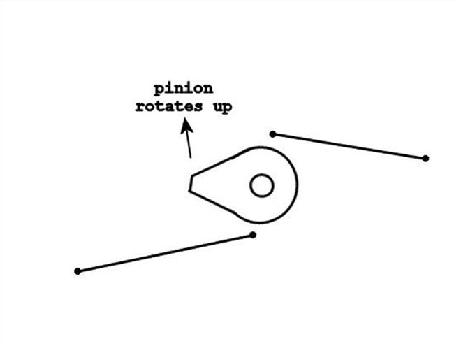
You can see from these diagrams that the pinion angle moves in a peculiar way (Figure 2). U-joints don't like the angles that are generated by a two-forward/two-reverse link system. It is possible to make the system work for a daily driver with zero performance advantages, but only with limited travel. On a two-forward/two-reverse system there are so many variables that can cause undesirable dynamic effects. The pinion is quite hard to keep within reasonable working limits, and the instant center moves around so much that there is no way for a normal human to track it, so calculating how forces are transmitted into the chassis is nearly impossible. It probably has more negatives than any other link design.
Locating DevicesEvery link system requires a lateral locating device of some sort to keep the rearend from moving from side to side in relation to the chassis. Some systems have it built in (for example, a triangulated four-link); others need an auxiliary system (like a Panhard bar). The locating device used determines the roll center, and the roll center changes the way that the truck acts and handles. So in a road-racing application, having a system with different mounting points offers a system with a tunable roll center. On a daily driver, the roll center isn't a major concern.
| FIGURE 3
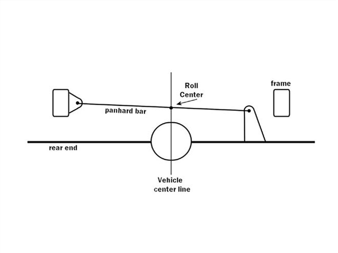
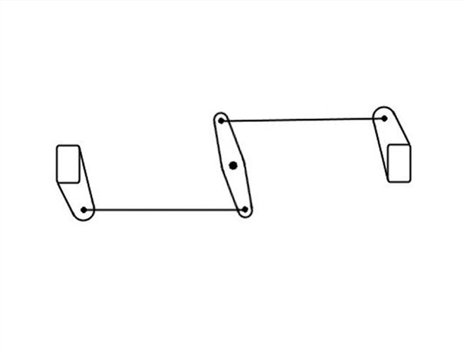
Panhard BarThe simplest of all the locating devices is the Panhard bar. It is mounted to the chassis at one end and the rearend housing at the other. The roll center is where the Panhard bar crosses the center of the rearend. So the higher the Panhard bar is mounted in the chassis, the higher the roll center and vise versa. The weak link of the Panhard design is that the single bar pulls and pushes the rearend from side to side as it runs through its travel. The best way to battle the push/pull effect of the Panhard is to run as long of a bar as possible and to be sure that the bar is parallel to the ground at half travel.
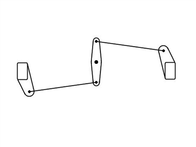
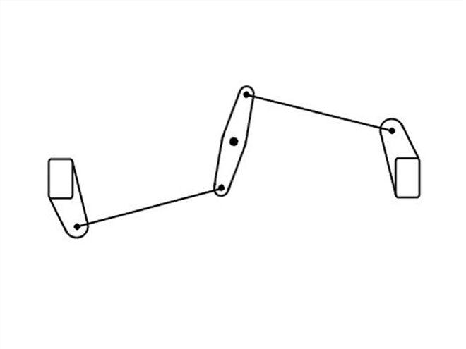
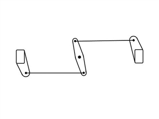
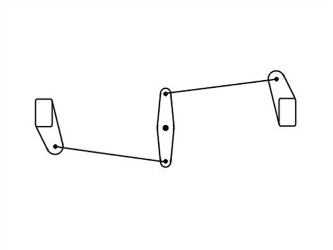
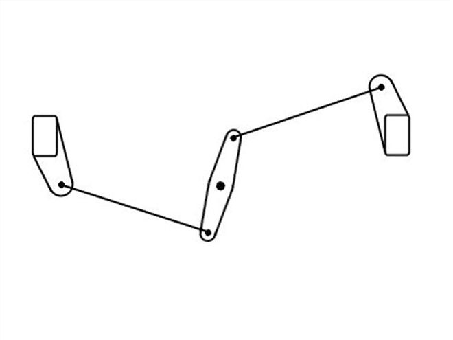
Watt's LinkThe beauty of this system is that if properly set up, the Watt's link has zero lateral movement and the roll center is easy to calculate. The center pivot of the link itself is the roll center.
On a properly set-up Watt's link, both bars will be parallel to the ground at half travel, but the center link itself will be over center. The center link will be straight up and down only at 1/4 and 3/4 travel. Also, because there are two bars limiting movement, the links need only be half as strong as a Panhard bar. It's not unrealistic to be able to use a 7/16 rod end on the connecting links. The center pivot should be as stout as possible because it "sees" the entire lateral load at that one point.
| FIGURE 6
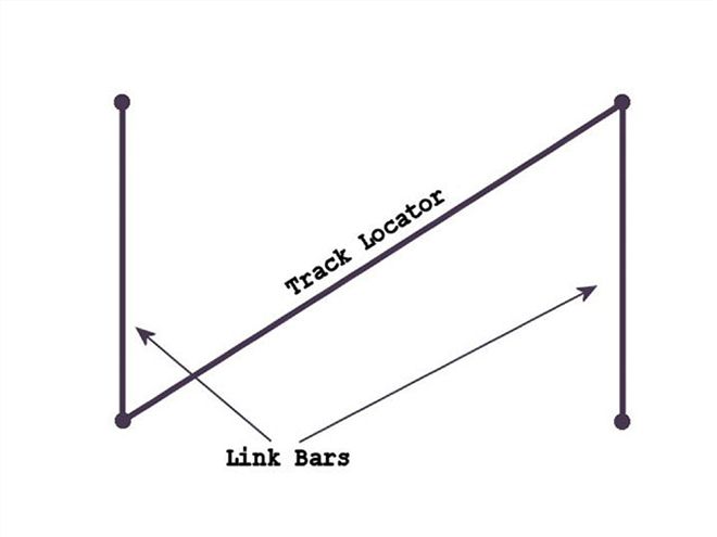
Track LocatorA track locator, or track bar, is typically used on drag cars because of its simplicity. A track bar is a bar that simply mounts to the rear link mount on one bar and the front link mount on the opposite bar, essentially creating a triangle that won't allow any lateral movement (Figure 6). The strange thing about the track bar is calculating the roll center. I have talked to some very knowledgeable suspension guys and cannot find a solid answer to demonstrate the best way to establish the roll center with this design.
By triangulating the upper, lower, or both sets of bars, you can limit lateral movement without the side pull of a Panhard bar. However, the bars must be triangulated as much as possible (up to 90 degrees to each other). It's tough to state a minimum angle because the length of the bars and the compliance of the bushings play a major role.
Triangulation Of BarsTriangulating the bars is a means of limiting lateral movement. And because it is a means of limiting lateral movement, it is also what sets the roll center. This one is just a little harder to explain. If you find the instant center (IC) of both upper bars and the IC of both lower bars on a three-dimensional plane and then take those two separate theoretical points and draw a line between them, you have the axis around which the rearend pivots. The point on the axis that crosses over or under the axle centerline is the roll center.
To make things easy, let's just assume that the roll center is very near the height of the triangulated bar ends that are nearest each other. For example, if the upper bars are triangulated and are mounted close to each other on top of the third member, the height of those joints is fairly close to the roll center.
So, if a low roll center makes for better handling (via more weight transfer), how would you lower the roll center on a triangulated link system? Triangulate the lower bars. A gentleman by the name of Satchell came up with this design to help trucks with limited space achieve a lower roll center. To properly set up a Satchell link, the lower bars must be triangulated with the bars coming to a point at the chassis, not the rearend housing. By doing this, the roll center stays "coupled" to the chassis and not to the constantly moving rearend housing. By having a roll center that is constantly moving up and down, the chassis can feel twitchy. Again, this isn't too much of a concern on a daily-driven, 'bagged truck, but it's good dinner conversation if you're truck is supposed to handle well.
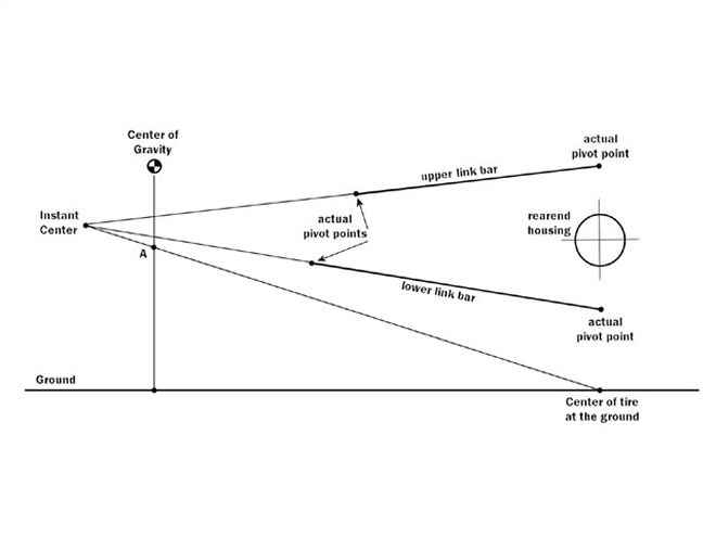
| FIGURE 7
Designs In Practice
Instant CenterAny time two or more links, bars, arms, or any other types of locating devices are employed, there will be an instant center (IC). The IC is found by extending an imaginary line through the points of each individual locating device until they meet the imaginary line of another related locating device. The point at which they meet is called the instant center or instantaneous center. Take for example a simple four-link. From a side view, the four-link appears to have only two links. If you were to extend an imaginary line through the pivots of each individual bar, at some point those two lines will cross. The placement of the IC is what determines where the forces generated by the tire/rearend relationship will be transmitted to the chassis. By moving the IC forward or backward or up and down, you change what type of driving the suspension excels at. This is the most important theoretical point to understand in the world of suspension design.
A properly set-up three- or four-link will have an instant center that is somewhere in front of the rearend. By moving the IC front to rear, you change the amount of force applied to the chassis. By moving it up and down, you can dial in the desired amount of antisquat. The position of the IC combined with bar length determines what it is that the link system excels at. A longer bar will allow more travel (but at the cost of energy transfer), while a shorter bar has less travel capability but more force transfer (think off-road truck versus a drag car.) Since most of you will probably be building a daily driver with adjustable ride height, the system should be somewhere in the middle. A medium-length bar with the IC around the front bumper at half travel is a very neutral system. It is essentially how Detroit has been doing it for years.
Also note point A point is a percentage of the center-of-gravity line (Figure 7). That percentage is the measure of antisquat. When a truck accelerates, weight is transferred to the rear, making the suspension "squat" from the extra weight. This chassis movement can be minimized or completely eliminated by using geometry to negate the squatting effect. On any rear suspension system (assuming it is a full-forward system, even a two-link), moving the IC higher will produce a higher percentage of antisquat, making the truck not squat as much during acceleration. A lower IC will have a lower percentage, and the truck will squat more. Going overboard and running the bars high in the front in order to negate any squat will induce excessive roll oversteer, making the truck less stable while cornering. It is not so important to calculate antisquat for a daily driver; it's more important you understand that it exists.
Roll CenterEvery suspension design has a point at which the truck "rolls" around when leaning from side to side. A higher roll center (relative to the center of gravity) will make the truck lean less in a corner, and a lower roll center will lean more. You might at first think you need a high roll center in order to eliminate excess body roll so the truck handles better, but that's not necessarily the case. When the chassis leans to the outside while cornering, the leaning adds extra weight to the "loaded" outside tires, increasing traction. To have more weight transferred onto the "loaded" tires offers better cornering traction but at the cost of excess body roll (this is where antisway bars come into play.) Calculating roll center is not so important for a daily driver, but knowing it exists and understanding how it can be changed is helpful when designing a quality system or if you intend on speeding around corners in your sport truck.
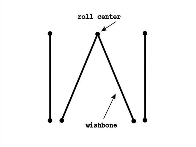
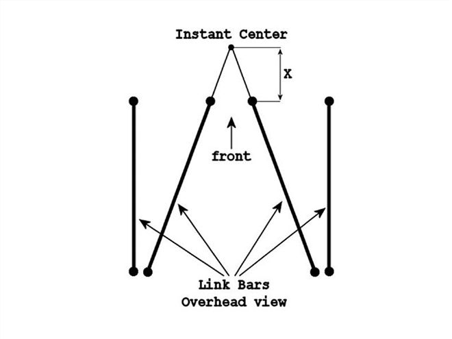
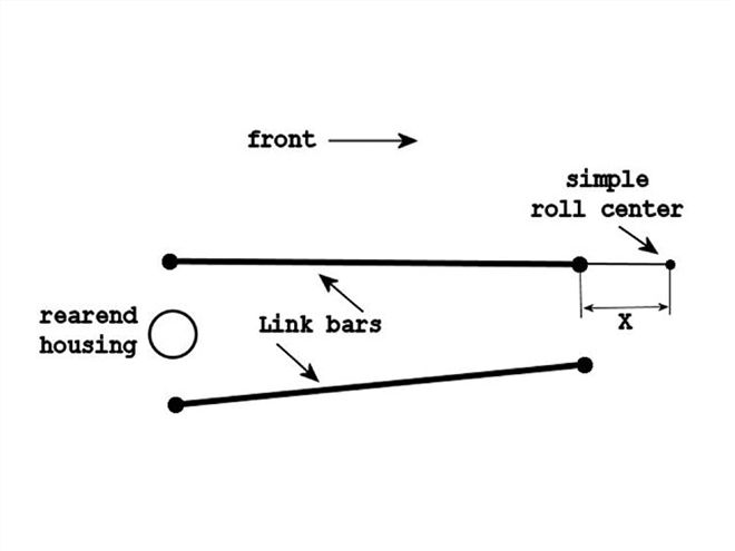
To find the "simple" roll center of a triangulated link system, you would first find the instant center of the overhead bars (Figure 10). Then, find the distance past the bars of the IC. From there, you would input that distance into the side view. That will give you a close enough roll center to figure from. From the side view (Figure 11), you can see that as the suspension runs through its travel, the roll center will move slightly up and down. That is not necessarily bad, just something to take note of.
From an overhead view, you can see that the roll center is or isn't centered to the chassis depending on the suspension design (Figure 11). And from a side view (which looks just like a nontriangulated link system), you can find the height (the single point of the wishbone.) An off-center roll center should be avoided if any performance is desired. Mounting the single point off center from the truck is not recommended because having an off-center roll center makes the chassis "think" that it's heavier on one side than the other. This can be interesting when driving aggressively on a windy road.
On a side note, a wishbone can take up a lot of extra space to properly set up on a truck designed to lay frame because of the need to mount the single point in the center of the chassis. As a rule, if the truck has a one-piece driveshaft, the system will take up more room than necessary.
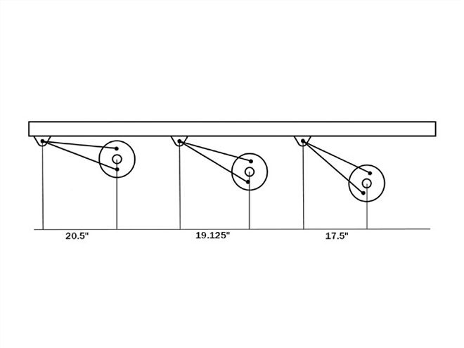
| FIGURE 12
Roll SteerGeometry being what it is, all suspension systems have a steering effect that is induced when one wheel is higher in relation to the chassis than the other; generally this happens while cornering or "hitting sides." It also comes in two different flavors: roll oversteer and roll understeer. Oversteer will steer the truck farther into the corner, causing it to feel as though you have turned the steering wheel too far. Understeer does the exact opposite, needing more input from the wheel to keep on course. Understeer is generally more desirable for a stable-feeling truck, but it's not always that simple. Roll steer is somewhat important to be aware of, as a poorly set-up system can become nearly undriveable if there is too much roll steer of either type. You can see how the wheel moves forward and back in the chassis as the suspension runs through its travel (Figure 12). If one wheel were up and one wheel down, the rearend would have its own steering input, similar to a Radio Flyer wagon. A commonly overlooked characteristic of three- and four-links is the distance that the bars are mounted across from each other. In every case, it is desirable to mount the bars as far to the outside of the axle as possible. Mounting the bars this way helps to minimize roll-steer issues as well as offers more support for the rearend. Top-to-bottom mounting distances are much more complicated and less of a concern. Just try to keep them about 6 inches or so above or below each other at the rearend.
The Big CompromiseFor 99 percent of us, a well thought-out neutral system (24- to 36-inch-long bars with an IC around the front bumper) would offer some really good performance. It's the 1 percent who are looking for every last ounce of performance that would need to start worrying about instant center and roll steer. So how should you set up your suspension to do what you want it to? First off, understand that you cannot have a system that does everything the best. You have to find a compromise. For example, an independent suspension can handle better and drive smoother than a straight-axle rear suspension. But, a straight axle will launch harder and withstand higher power from the engine.
Here are some basic starting points: If you're building a long-travel off-road truck, then bars up to 48 inches long and an IC a few feet in front of the truck is best for neutral handling throughout the entire 2-plus feet of travel that you might need. On a road-race truck, shorter link bars with a low roll center and extra attention to roll steer would be a good place to start. And for drag racing, a two-link would work well (there's no cornering in drag racing) or a four-link with 18- to 24-inch-long bars and an IC that's in the middle of the chassis and 6 to 10 inches from the ground. Understand that these are just basic starting points. The dynamic relationship between the ground, tires, rearend, link design, and chassis is constantly changing, and we can only hope to find a fair compromise that works well for what we're trying to accomplish.
Finally, before settling on a suspension design, be honest about what you need your truck to do, not what you want it to do or how you want it to look. We all want our trucks to be the very best, but the actual use of your truck should be considered in your suspension design. If you want a truck that can put 1,000 hp to the ground using a limited-travel suspension design and still be able to drive it to work every day, you're going to suffer with an ill-driving truck in most situations. The same goes for a daily driver that has too much suspension travel-it just won't drive very well that way.
 | rear Suspension Design rear Suspension
There are many ways to lower a truck, and the options multiply with rear suspension design-especially when you're dealing with an adjustable suspension with airbags or hydraulic cylinders. One only has to walk among the rows of lowered trucks at any show and peek through the holes in the bed floors to see the plethora of ways to make the rear axle of a truck cycle up and down. If you have ever wondered which linked suspension design is right for your truck and the type of driving you intend to do with it, this article will provide not only the answer but also a good definition of how a suspension should work. By the time you're done reading, you'll be able to pick a rear suspension design that will offer a good compromise between ride quality, traction, handling, and of course, getting your truck flat on the ground.
Suspension Designs
 | FIGURE 1
Full Reverse and two-Forward/two-Reverse Link Systems
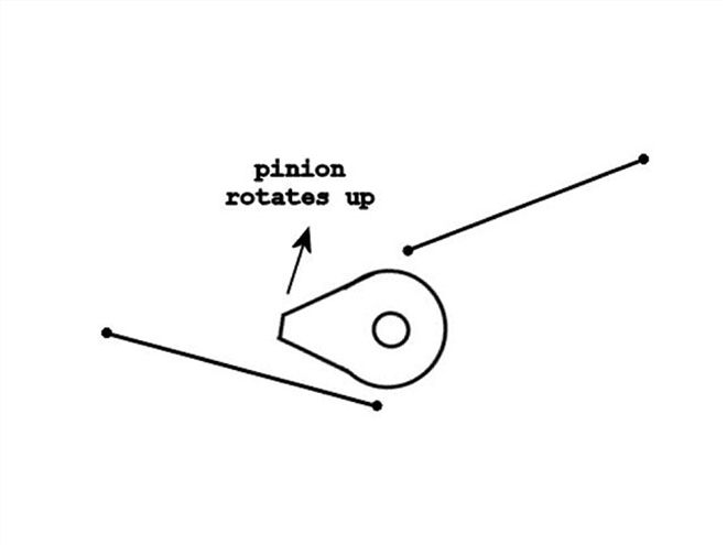
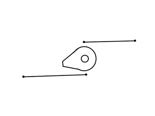
 | FIGURE 3
Panhard Bar
 | FIGURE 6
Track Locator
 | FIGURE 7
Designs In Practice
 | FIGURE 12
Roll Steer