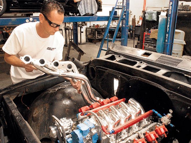
| ls1 Header Install test Fit
It takes energy to push disorganized exhaust gases out through a vehicle's stock exhaust manifold. Headers don't make horsepower; they relieve the engine from the task of straining itself while extruding gasses through stock exhaust manifolds. Installing properly designed headers will relieve the energy previously wasted by pushing the exhaust gases. This increase in efficiency of installing headers can be thought of as a free horsepower gain.
Jamie Joyce, manager of Doug Thorley Headers, will walk us through the Doug Thorley Headers design and manufacturing process as these first prototype headers were fitted for the LS1 V-8 5.7L, PN324Y-C, that were used for the '67 Chevy C10 project Nightmare.
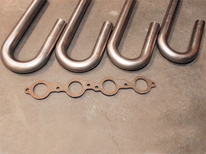
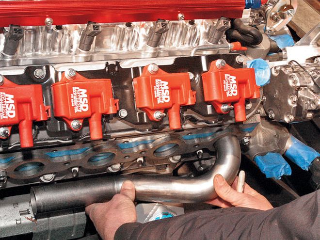
| Doug Thorley Headers foundation are the 3/8-inch thick flame-cut flanges and 1-5/8-inch-diameter 14-gauge mild steel primary J-tubes.
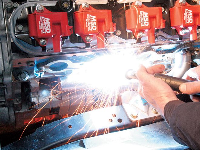
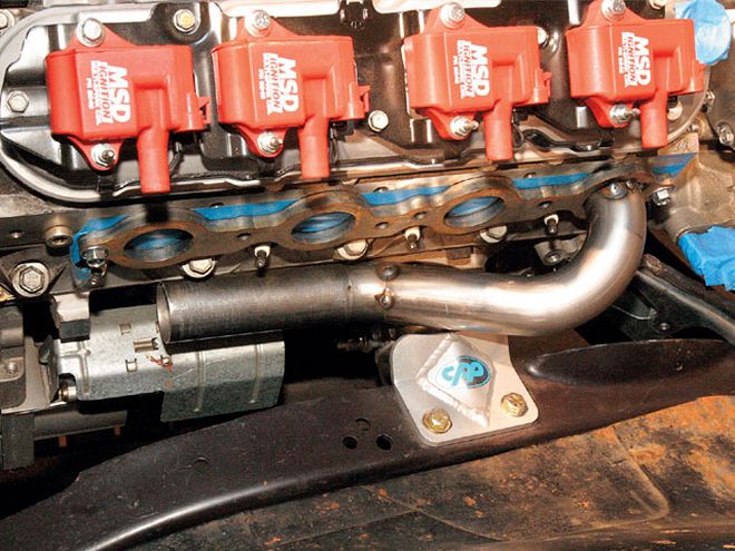
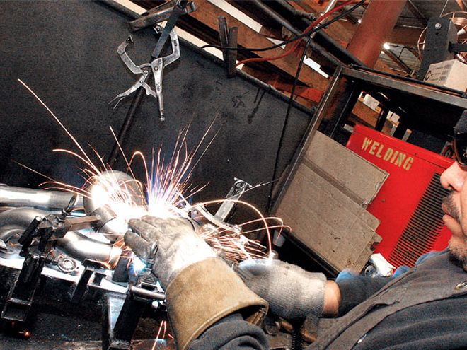
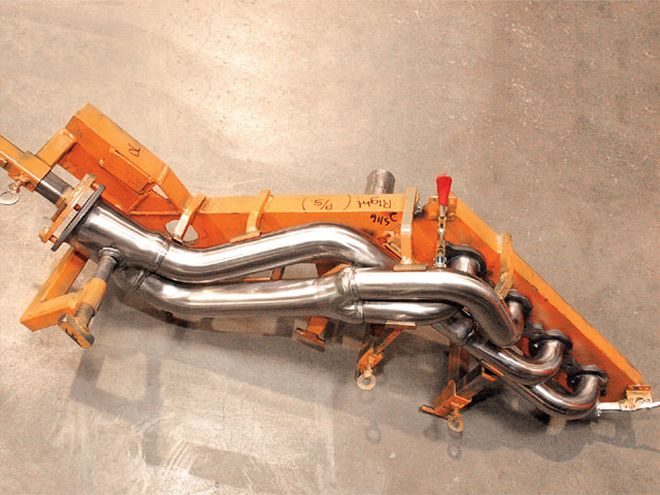
The foundation of the Doug Thorley Tri-Y headers is the 3/8-inch-thick header flange. The 1-5/8-inch-diameter 14-gauge mild steel primary tubes were mocked up using 14-gauge J-bend tubes. After the flange was bolted to the LS1 cylinder head exhaust port face, the J-tubes were cut to provide exact angles to avoid clearance issues, with such obstructions as the steering shaft, framerails, crossmember, and starter. After the header's four primary tubes were cut, they were divided into pairs: two tubes that merged into two separate collectors. A single tube emerging from each of the primary collectors merged into the third and final collector. With the pieces cut and fitted, they were then tack-welded together. A fixture was made to support and hold the cut pieces in place while the multiple pieces were welded. After the header was welded into the fixture, it was removed, then each weld was carefully inspected.
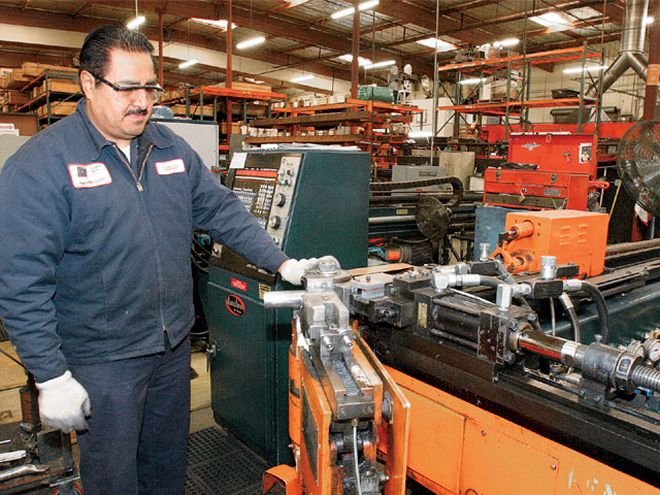
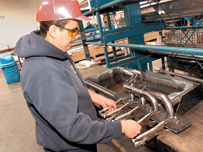
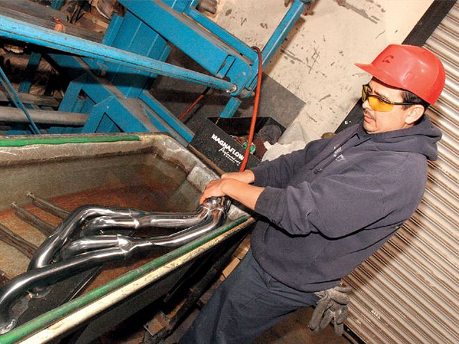
After the prototype headers were made, they could be traced and duplicated into a CAD program. The automated CAD tube benders then automatically rotate, index, and bend each tube to its correct and precise configuration. The pieces were then laid into the fixture and welded. After the welds were inspected visually, they were submerged and pressure tested for any leaks. After everything checked out, the headers were sent to the polisher before they were chromed or ceramic coated.
Chrome Coating:Protects the header surfaces from initial rust or corrosion, but not for extended life. It is not intended to be "show chrome," as it will discolor upon initial fire-ups, and this is normal. Chrome headers are still guaranteed against manufacturer's defects and workmanship.
Ceramic Coating:Doug Thorley ceramic-thermal coating protects the header against the elements and can take temperatures as much as 1,400-degrees Fahrenheit. This coating keeps heat inside the tubing, thus promoting velocity while absorbing up to 40 percent of the engine's temperatures. This keeps the engine running cooler and helps in all areas where heat is the issue. A ceramic coating of 3 mm is applied inside the header tubes.
Tri-Y Headers Theory:The Tri-Y header gets its name from having three total collectors, instead of just one. In this design, the primary tubes are welded to the flange, then two of the primary tubes go into a collector, and the other primary tubes go into another collector. From these two collectors, a single tube emerges from each collector, then these secondary tubes go into the end or final collector. Each Tri-Y header is designed to match the synchronization of the engine's firing order, thereby maximizing exhaust scavenging. This design creates the best torque and horsepower gains.
From the Driver Seat:The exposure to Doug Thorley Headers Tri-Y design, manufacturing procedure, and testing was very informative. Since '67 Nightmare was not finished, we were not able to perform any dyno pulls. But, we did get some numbers that were presented to us: 30 horsepower at 35 lb-ft of torque.
Doug Thorley LS1 5.7L V-8 for a '67 Chevy C10 pickup.
Parts Used: PARTS USED: Doug Thorley Tri-Y Ceramic, PN 324Y-C $580.00
 | ls1 Header Install test Fit
It takes energy to push disorganized exhaust gases out through a vehicle's stock exhaust manifold. Headers don't make horsepower; they relieve the engine from the task of straining itself while extruding gasses through stock exhaust manifolds. Installing properly designed headers will relieve the energy previously wasted by pushing the exhaust gases. This increase in efficiency of installing headers can be thought of as a free horsepower gain.
Jamie Joyce, manager of Doug Thorley Headers, will walk us through the Doug Thorley Headers design and manufacturing process as these first prototype headers were fitted for the LS1 V-8 5.7L, PN324Y-C, that were used for the '67 Chevy C10 project Nightmare.
 | Doug Thorley Headers foundation are the 3/8-inch thick flame-cut flanges and 1-5/8-inch-diameter 14-gauge mild steel primary J-tubes.
The foundation of the Doug Thorley Tri-Y headers is the 3/8-inch-thick header flange. The 1-5/8-inch-diameter 14-gauge mild steel primary tubes were mocked up using 14-gauge J-bend tubes. After the flange was bolted to the LS1 cylinder head exhaust port face, the J-tubes were cut to provide exact angles to avoid clearance issues, with such obstructions as the steering shaft, framerails, crossmember, and starter. After the header's four primary tubes were cut, they were divided into pairs: two tubes that merged into two separate collectors. A single tube emerging from each of the primary collectors merged into the third and final collector. With the pieces cut and fitted, they were then tack-welded together. A fixture was made to support and hold the cut pieces in place while the multiple pieces were welded. After the header was welded into the fixture, it was removed, then each weld was carefully inspected.
After the prototype headers were made, they could be traced and duplicated into a CAD program. The automated CAD tube benders then automatically rotate, index, and bend each tube to its correct and precise configuration. The pieces were then laid into the fixture and welded. After the welds were inspected visually, they were submerged and pressure tested for any leaks. After everything checked out, the headers were sent to the polisher before they were chromed or ceramic coated.
